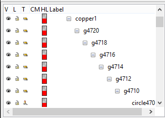
What to say. So much work was still needed to be done ...
It is difficult for me to read such a long text and understand it. Perhaps I did.
I've reopened my original svg file using Inkscape and yes, I can see that there is no upper contour line there. This is especially good to see in "Icon view".
This really looks like an Inkscape bug.
Is there some file (created with Inkscape from the scratch) that can be used to import into the Fritzing program (and does not require so many additional edits)?
In fact, I mean, of course, a set of three files (for breadboard, PCB and schematic).
Because the template that comes from the Fritzing export is not 100% OK (at least I think it).
This would be very useful, there would be seen the necessary structure of objects (silkscreen, copper1, copper0, parts, pad size and so on). The structure should be as simple as possible, with the minimum number of nested layers. I was almost shocked when I saw the expanded structure of objects of the PCB file ...
As part of such a template, of course, a description of the necessary modifications that need to be done with a plain text editor (such as removing "px" units) would of course be required.
I think it would make it easier for beginners and it would also make it easier for you to work on correcting their work.
Luboš