Over all a nice job (I have a previous part from someone but I like yours better  ). These are a nice cheap display and there is a nice library available from Sparkfun. That said your part has a few issues (mostly in schematic, and mostly style, yours works just fine mostly). Both breadboard and schematic are lacking the correct layerIds. The only thing I know that affects is svg export of the part from Fritzing will fail. The holes in pcb should be labeled nonconn0-4, with a stroke-width of 0. This is secret Fritzing code that causes the gerber output to only put the hole in the drill file (yours will work but it puts copper on the copper layers which the drill will then drill out). I changed schematic to look like this (mine on the left yours on the right):
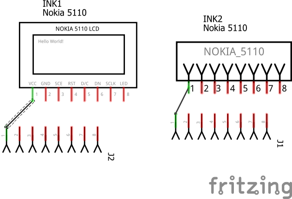
The wire on yours connects to the middle of the pin (rather than the end as is desirable) because you don’t have a terminalId defined in the schematic svg. Without the terminalId the wire connects to the center of the .1 in long pin which isn’t what we want in this case. Below is a modified (with a new moduleId so you can load both parts at once) copy of your Nokia 5110_INK_Display_BtmRow.fzpz part with my changes (in addition I rescaled them all to the standard scale as well as fixed the layerIds).
Nokia 5110 INK Display_BtmRow.fzpz (7.3 KB)
Peter