Quantcast
Channel: fritzing forum - Latest posts
Viewing all 31541 articles
Browse latest View live

Arduino Pro Mini Disappears From Breadboard View But Stays In Others

$
0
0

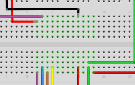
I'm running 0.9.3b on Ubuntu. When I place a Arduino Pro Mini on the breadboard it shows up, but after I close and reopen the file the Pro Mini is gone from the breadboard view, but is still in the PCB and Schematic views. If I place another Pro Mini on the breadboard, the part is duplicated in both the PCB and schematic views. Many of the holes stay green on the solderless breadboard in the Breadboard view though, like the Mini is still there but not being drawn.

I'm using the Pro Mini from the Arduino section.


Arduino Pro Mini Disappears From Breadboard View But Stays In Others

$
0
0

This happened to me too but it is actually there and the sketch works as expected so I didn't worry about it and kept working.

Raspberry Pi Zero Fritzing Part

$
0
0

The zero available in the parts bin appears to be correct at first glance (I didn't go as far as to produce gerbers and check hole sizes though). I'd start there.

Peter

Solved: No schematic or pcb rats nest lines for adapter part

$
0
0

Solved

When I got the new version far enough along, I did some diffs with the original failing version. I noticed an error in the part.fzp file. I knew I did not want real schematic and pcb views, but somehow I had duplicated the icon svg references for those layers, instead of the breadboard svg. Swapping that got the failing version to work.

2-by-x-header2breadboard.fzpz (2.9 KB)

Now I can expand it to the full headers / carrier I want.

In the process of testing though, I confirmed that this only works when the part family is set to Breadboard. Anything else wants to put a representation for the part on the schematic and pcb views. Instead of just the (rats nest) wires.

Modem GSM/GPRS Ai A6

$
0
0

You are welcome. About half an hour or less for me to do probably a lot longer for you if you aren't familiar with the tools.

Peter

Arduino Pro Mini Disappears From Breadboard View But Stays In Others

$
0
0

If you would post the fzz file I'll have a try on Windows and see what happens. This may be a fault in the part, if the layer id is missing or it isn't properly registered with the parts database I've had this happen (works in the first session but not when its saved).

Peter

How to Make Capacitive Touchpads in Fritzing

$
0
0

Just to be clear... Can I do the following :

• import an SVG into the copper layer to form my pad shape
• place a via on top of this copper shape and another off of it somewhere
• connect a trace from some part to both vias in series
• select the first via ( on pad shape ) and 'convert to bend point'
• select trace between bend point and the remaining via and 'delete wire up to bend point'
• delete obsolete via

Basically what I'm asking is; does it matter that Fritzing doesn't know that I am connecting to the SVG pad shape? They are on the same copper layer and appear on top of one another, but I'm not sure how this affects the creation of gerbers and the subsequent pcb fabrication.

RJ11-6p6c pcb socket

$
0
0

Hi Peter,
The module "Properties Family" reference is "SparkFun-Connectors-RJ11-6-PTH" path="C:/temp/Dropbox/Fritzing/fritzing-parts/core/sparkfun-connectors-rj11-6-pth.fzp">. It creates the following PCB hole layout:

The bottom notch requires the socket to be positioned on the edge of the PCB, otherwise it would be impossible to release the plug.
My application requires the socket to be positioned within the boundaries of the PCB and therefore require the top notch connection socket.
I found the following with a top notch at http://uk.rs-online.com/web/p/rj11-connectors/7350282/ for which the following PCB layout applies:

Any make with associated pcb layout would suffice as long as it has a top notch.
Hope I have made myself clear in answering your further questions.
Rgds
Dick


Arduino Pro Mini Disappears From Breadboard View But Stays In Others

Disable Auto Update

$
0
0

Is there a trigger to disable the auto update feature on the app? It is not apparent from the normal menu options offered.

Arduino Pro Mini Disappears From Breadboard View But Stays In Others

$
0
0

Well first the good news, your fzz does the same for me and the exported mini part is configured oddly which I think may be the issue, its layer name is breadboardbreadboard which is generally the special family for breadboards and may be the problem (as fritzing treats it specially) and it has some of the pins set to female which is also unusual (normal only on breadboards). However when I pulled all three of the versions that parts search found in the parts bin in to a sketch and made some connections to each in breadboard and saved it (on Win7 with .93b and the latest parts downloads) and saved and reloaded the resulting fzz it displays properly unlike yours. I'll poke further and see if I can spot the problem. Odder yet I just discovered the third version is in fact the exported part from your fzz which appears to work fine on Win7 after being exported from parts manager. I'll probably try recreating your entire sketch from scratch, since it is also possible this is a database corruption problem (usually caused by making changes in more than one view) and the only know way to fix that is start again unfortuntatly.

Peter

Arduino Pro Mini Disappears From Breadboard View But Stays In Others

$
0
0

OK, I think I have figured out whats wrong. I think the problem is your positioning of the mini on the breadboard. If you do that as you have the middle pins (between the two rows on the edges) connect (unlike real life I expect) to the pins on the breadboard shorting some of the pins to each other. That likely causes database corruption and causes the part to disappear as a side effect. The solution is to move the mini down the breadboard so the pins don't short. With the mini as originally set on the breadboard gnd is shorted to +5V via the right side middle gnd and +5V pins (which connect to the 5 pins all bussed together on the breadboard). I expect in real life there aren't pins there and there isn't a problem, but fritzing makes the connection if the pins are on top of each other and that likely causes the problem. To solve that I moved the mini to the end of the breadboard so the extra 6 pins hang over the bb area that has no connectors so they won't short. I also used the power strips on the bottom to distribute power and ground although direct connections will work the same in practice. Now it appears to load and save correctly (at least for me on Windows :slight_smile: ). As a side issue, I think your connections to the battery charger are incorrect (I'm not sure mine are any better though, you need to look over the documentation for it :slight_smile: ). As well I think the display may be 3.3V only and thus may need level translators to and from the 5V signals on the mini (or a 3.3.V mini and a 3.3V output battery charger) again check the documentation (Adafruit's is usually excellent!) to see if it is 5 volt tolerant (many displays are not!). Hope this helps!

arduino_pro_mini_problem_fixed.fzz (18.2 KB)

Peter

RJ11-6p6c pcb socket

$
0
0

I see the problem, but the top notch one seems fairly different. The sparkfun version is on .1 in centers. The top notch one seem to be .1 in row but some odd value center (not 2.54 mm but something smaller likely 1.69mm if I'm calculating correctly) which seems odd to me as I would expect all rh11s to have the same footprint. It should be easy enough to modify the sparkfun pcb svg to match this particular plug but I'm not sure that will apply to any others. A quick look at digikey indicates it is manufacturer specific. The first one I found (from pulse) matches this layout, the next one is different again from either this or sparkfun's, how odd. If you are good with this particular layout I can modify the sparkfun pcb svg to match it I think. I see that there are also straight up (as opposed to 90 degree such as these are) plugs where the wire would go straight up from the surface of the board rather than parallel to the board, would that do you better perhaps? I expect connecting and disconnecting would be easier for the user if it is in the middle of the board somewhere (and probably their footprint is different yet again :slight_smile: ).

Peter

2 row header to DIP footprint

$
0
0

An adapter 2 allow connecting a 0.1 inch 2 row header, up to 10 columns, to a breadboard. Longer can be handled by multiple adapter parts.

2-by-10-header2dip.fzpz (3.7 KB)

2 row header to DIP footprint

$
0
0

Looks and works good! You probably want to copy the breadboard svg into icon svg so the icon matches the breadboard view though.

Peter


Arduino Pro Mini Disappears From Breadboard View But Stays In Others

$
0
0

Awesome, thank you very much. It opens fine for me too, and I appreciate suggestions on the circuit layout. The Pro Mini I'm ordering is 3.3 volts, so I think I'm in good shape there. I'll double check that the 3.3 pinout matches the Fritzing part though.

This was all very helpful. Thanks again.

Disable Auto Update

$
0
0

I assume auto update is the check for new parts on github (which I don't know how to disable although someone else may) as opposed to auto save which can be disabled in edit->preferences->General->Autosave? On the Mac shutting down networking has enabled Fritzing to run when the ssl library is too old to connect to github, but that is a bit extreme (but a possible solution) :slight_smile:

Peter

Arduino Pro Mini Disappears From Breadboard View But Stays In Others

$
0
0

There is a pro mini 3.3V Fritzing part available if you enter the search term arduino pro mini in parts search (it may be in Sparkfun somewhere as I don't see it in Ardunino but it does come up in search). You likely need to see if the 3.3V mini will take 5V as its raw voltage or the lipo charger/regulator comes in a 3.3V version though. Doing without level translation is a good bet as translation is generally a pain.

Peter

555 IC Will not align with pins in center of Breadboard

$
0
0

Peter,

I started a new project, with the grid setting at 0.1, and it worked. I don't know why it's working now
while it didn't work on the the first project that I started. I didn't do anything differently.

I can't get the wire jumpers to form 90 degree bends. The bends are either less than or greater than
90 degrees. Do you have any suggestions for this problem?

Thanks,

Gary

Newbie: How to add Wemos Mini

$
0
0

Hi,

I am a newbie in fritzing and like to have the templates for my Wemos Mini d2. But I only read about problems and not if this is really fixed and how to add it to my Fritzing.

Please help.

Best regards,
Gert

Viewing all 31541 articles
Browse latest View live


<script src="https://jsc.adskeeper.com/r/s/rssing.com.1596347.js" async> </script>