Quantcast
Channel: fritzing forum - Latest posts
Viewing all 32452 articles
Browse latest View live

Creating QFN-24 3.5mm x 3.5mm

$
0
0

Thank you old grey. I used the part that vanepp sent me. And i think its look good for now. I will send it out for fabrication. Fingers crossed that the chip will solder well onto the board. Thank you so much :slight_smile: I have attacehd the PCB to show how it looks like

Acquisition Module Mark 1a.fzz (494.3 KB)


Creating QFN-24 3.5mm x 3.5mm

$
0
0

You have to reset the grid and straighten the traces.

Be 100% sure that it's right, as there is no use doing it wrong, by checking the Gerbers. There are online Gerber viewers, or you can use the free Gerbv, or even print it out and check it.

Creating QFN-24 3.5mm x 3.5mm

$
0
0

Thank you Old_Grey. This time i printed out the circuit onto a PDF just to see if it somehow aligns to the chip i have. It seems to be more or less accurate :).

Creating QFN-24 3.5mm x 3.5mm

$
0
0

If you are going to hand solder this, then I'm glad I was lazy and left the pad width at its current .22mm instead of the .3mm recommended in the Infineon part. While it will make placement a bit more tricky there is a touch more space between pads to avoid solder bridges. I see you have connected the heat sink copper on the bottom of the chip to ground which is probably a good bet. The data sheet calls it pin 0 but doesn't show it as connected to anything, so it shouldn't mind being ground. Good luck, and tell us how you make out :slight_smile:

edit: Looking closer at the gerber output with gerbv, you may want to straighten the connections in to the thermal heat sink. They both bend a bit from the vertical and thus reduce the spacing between pins. Same with many of the other connections in to the IC pads. Given the distances I think you want as much separation as possible to avoid solder bridges (although the two on the copper pad are probably the ones most at risk as they will be under the chip and not accessable).

Peter

Creating QFN-24 3.5mm x 3.5mm

$
0
0

I'm not sure if Van's 0.2mm extension to the pad is enough, but if the pad protrudes past the body of the part you might be able use a soldering iron and wick the solder under the chip. Then just put a via in the middle and wick it to the center GND pad from the other side.

By the sound of it he has the solder paste sorted and just heats it with air.

ITDB02 TFT Arduino Mega Shield v2.0 and mirrored Arduino mega

Creating QFN-24 3.5mm x 3.5mm

$
0
0

Hi Vanepp, Thanks again for the advice. I can use both methods to solder. Personally i was about to use the solder paste + heat gun method as that worked for me before with the breakout board. And for the current design, i have requested for production already , but its with a silk screen. So this should prvent any kind of solder bridges. The trickiest part to solder is definitely the QFN 24 chip. I tried to make the connections as straight as possible. I somehow missed to see the bent connections at the pads. Thats a bit upsetting for me. I have sent the PCB for manufacture which should arrive for july 13th. I hope i can give a good results :slight_smile:

IBT-2 Motor Driver 43A H-Bridge Drive

$
0
0

Can I get a picture of IBT-2 Motor Driver 43A H-Bridge Drive


Creating QFN-24 3.5mm x 3.5mm

$
0
0

They aren't that far off, its just that all the distances are small and every little bit helps :slight_smile: . Hope this works for you.

Peter

IBT-2 Motor Driver 43A H-Bridge Drive

$
0
0

Assuming that you are looking for a fritzing part (rather than a picture) for the motor driver, the answer is that there seems to be one (the third or forth article here has a picture of it) but I can't see the part anywhere. You might try contacting this person and asking if the fritzing part for the driver is available. A google search on "fritzing part IBT-2 Motor Driver" turned this article up.

http://archive.is/6zqd8

Peter

IBT-2 Motor Driver 43A H-Bridge Drive

$
0
0

fritzing part IBT-2 that’s what I’m looking for.
Any help out there?
Thank you

IBT-2 Motor Driver 43A H-Bridge Drive

$
0
0

Your best bet would probably be to try and contact the person that did the blog post. He obviously has a fritzing part for the driver and may be willing to share it. Otherwise you would need to create a part for it (which isn't all that easy unless you are already experienced at making parts).

Peter

IBT-2 Motor Driver 43A H-Bridge Drive

IBT-2 Motor Driver 43A H-Bridge Drive

$
0
0

Again a picture of the fritzing part but no part source to be found. However someone else to ask if the part is available ...

edit: If you manage to find a part, please post it or a reference to it for others ...

Peter

DB15 VGA Part Male and Female

$
0
0

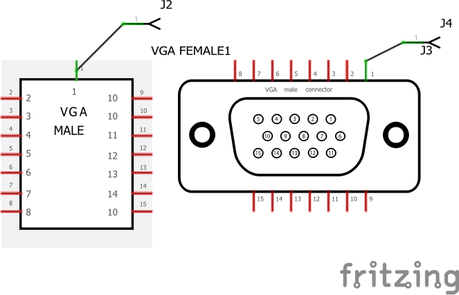
Welcome to parts creation hell :slight_smile: , sounds like you have already been bitten by the monsters but prevailed, hope you continue creating parts. That said there are some problems (none terribly serious):

1) Both parts have the same moduleid so you can only load one or the other. To fix, edit one with parts editor, save as a new part (which creates a new moduleid) and export it, then copy your svg files over the ones fritzing created (except for the fpz which you need to edit to make the changes to the metadata if you don't do that in parts editor).

2) The schematic svg is missing the terminal defiinitions (they are in the fpz) which causes this:

note on your original the line terminates in the center of the pin. Setting a terminalid to the end of the line terminates it on the end as is desirable.

3) The pcb has copper rings around the mounting holes (which perhaps you wanted for some reason?) and the hole is .128in rather than .125 (1/4) which the data sheet calls for (found in the gerber drill output). The pin holes will work for this particular connector, but there is an Amp one (data sheet here)

http://www.te.com/commerce/DocumentDelivery/DDEController?Action=srchrtrv&DocNm=1734344&DocType=Customer+Drawing&DocLang=English

which is the largest of those on digikey at 3/64s so I increased the hole size to 0.046837 to fit that or any of the smaller ones (the footprints are otherwise standard). As well there was no silkscreen so I added the outline of the part to silkscreen to aid in component placement on the pcb (this part sticks out a lot further than the pins indicate).

I fixed all of these and did a bunch of internal cleanup (this was based on an older part and still had separate copper0 and copper1, and fritzing export's usual deep levels of group nesting) and added a better (if not by much :slight_smile: ) breadboard view, although I agree probably not many will use it. Note the new breadboard svg uses bendable legs, so parts editor (and modifying it with Inkscape unless you post process it to remove the style commands which I did) will break it. If you have questions about it feel free to ask, always glad to encourage parts creation. My updated versions:

DB15 VGA female.fzpz (24.2 KB)

edit: just realized schematic on the male is wrong, will correct it and repost. This one should be correct (if you have downloaded before seeing this comment. please redownload!). Well not quite, breadboard is incorrect as well. Sigh, third time lucky.

Peter


IBT-2 Motor Driver 43A H-Bridge Drive

$
0
0

I tend to skip over the question because I'm lazy, but now looking at it he might want a good top pic to make the BB view.

You can do a Goo Image search, but remember adding 1 word can get different results, like "IBT-2" isn't as good as "IBT-2 bridge". You could also search the chip and add bridge type stuff.

Creating QFN-24 3.5mm x 3.5mm

$
0
0

Will let you know Peter. You just saved my ass :slight_smile: . I had no idea how to create parts and do graphics. If i had to move to Eagle or Altium which had this part. It would take me weeks just to know the software.

Creating QFN-24 3.5mm x 3.5mm

$
0
0

For me (after struggling with parts creation for coming up on a year with lots of help from the other folks in here :slight_smile: ), only an hour or so with Inkscape and the data sheet. To someone new to parts creation a lot more of a problem. Once you are up to speed, parts creation isn't bad, it just takes a lot of effort and mistakes to get up to speed. It helps a lot if you are already familiar with a svg graphics editor like Inkscape (which I wasn't, and after a year still aren't, it wins with regularity :slight_smile: ) but even then fritzing has its share of things it dislikes that you need to trip over a few times

Peter.

Peter

Fritzing is crashing during Gerber export

$
0
0

I am having a problem where Fritzing just crashes and hangs when I choose to do a gerber export. When I look in the export folder it has only got as far as the pnp.txt file.

Does anyone have any idea what might be happening? It seems to be a problem with my file because I've tried this Fritzing project file and it exports fine.

I don't understand what is wrong with my particular file to cause these crashes.

( I have saved the osx crash report after force quit if this helps the developers at all. )

Fritzing is crashing during Gerber export

$
0
0

Have you waited an unbelievably long time? I know for me on Linux with complex Fritzing sketches it causes the program unresponsive message and asks if I want to force it quit all the time and not just during Gerber export (ground fill, opening projects, updating, undoing things, etc). I ignore those messages as they are simply the system not getting a response from the program because it is busy doing the last thing you asked it to do, they are not a result of the program not doing what you want.

When I have to fix peoples Windoors computers I expect it even more and I just walk away and hope that when I come back a half hour later things have completed.

Viewing all 32452 articles
Browse latest View live


Latest Images

<script src="https://jsc.adskeeper.com/r/s/rssing.com.1596347.js" async> </script>