You do realize that the parts Vanepp makes are just art work for use in Fritzing. These are not plans or boards to produce slip rings.
↧
6 wire slip ring
↧
Hello to you all, novice prop maker in the house!

↧
↧
Fritzing PART CREATION Video Tutorial Series
Fritzing Part Creation - Chapter9 - Using Photo and PDF for Parts
Using photos and PDFs for Breadboard view in Fritzing parts.
Generally not recommended, except for one-off parts.
↧
6 wire slip ring
Yep! Sorry if I didn't make that clear in my original post 
↧
Hello to you all, novice prop maker in the house!
Doesn't look that difficult, looks like 3 buttons (finding a wide one for the bottom may be exciting, but there are lots and lots of switches of all sizes available). They make LED bars similar to that, but they are typically either all one color or have red and orange on each end so you may need to use 8 square leds of different colors to get what you need, but again not that difficult (I expect they make multicolored leds in square although I've not used them). Both of those will interface to an Arduino without problem (just a minor matter of software  ). One of the mp3 player modules or a sound module for the arduino should be able to reproduce almost an sound on demand. I'm assuming you have or can make a suitable case (a toy with the correct case is a good bet for that). You would need a battery somewhere in it to run the arduino and the leds, again not difficult. I don't see anything that should be a show stopper (although that doesn't mean there isn't something ).
Peter
↧
↧
Hello to you all, novice prop maker in the house!
Actually there those 5mm rectangle LEDs which I've got from Mouser Electronics to complete the display, I was thinking finding the 3.3V volt mini and use that and just have it powered by 3v.
Plus I may just use the soundboard to make the LED light with the phaser sound and that's about it unless I use pin 13 for sound or pin 12 for it....multiplexing 16 leds are gonna be a challenge plus getting the finished display to be in the toy where the fake display used to be.
↧
Hello to you all, novice prop maker in the house!
Multiplexing pins isn't that hard. A 74hc595 8 bit shift register is the easiest, or there are led driver modules on ebay. If you search in the forum for 74hc595 there was someone else a while back needing them for led multiplexing. You may want to look at boost or boost/buck power modules (which basically take a varying input voltage such as a battery in and regulate it to 3.3V at %80 or %90 efficiency, you only need a boost/buck if the battery voltage can get higher and lower than the output voltage, for a lower voltage to higher you only need boost and for higher to lower only a buck which are both a bit cheaper than a boost/buck) some of them are very small and they smooth out power problems from low battery. I made a fritzing part for the square leds a while back, it is in parts submit somewhere (a forum search should turn it up). Sounds like you are well on your way :-).
Peter
↧
Hello to you all, novice prop maker in the house!
You could easily charlieplex 16 LEDs using 5 pins. Sound is actually the hard part from my experience. I found hacking a cheap MP3 player or buying a sound module was about the only way to add sound to an Arduino project.
Also for an 8mhz Arduino pro mini with its voltage regulator removed you can safely power it from a 3.7v lipo battery and it will run happily from fully charged at 4.2v all the way down to the 2.7v safety cut off on the battery and when put into low power mode and woken by the interrupt pins (pins 2 and 3) it can last for many months without charging.
↧
Download part for flame sensor
This should do what you need. Breadboard is somewhat odd in that the right angle connector is dual row so the pins are on .05 centers rather than .1

5-channel flame detector module.fzpz (26.4 KB)
Peter
↧
↧
Hello to you all, novice prop maker in the house!
I really don't want to mod the playmates Toy too much and it's redeemed useless the standard 2 AA battery compartment is fine and that's what I'm trying to do power all leds using 3 volts and the tones from the arudino and new SD card powered sound board, including the new LED indicator.
↧
Multiplexing 16 LEDS
Here's the issue I'm trying to make out how I multiplex all 16 LEDS and do what I need them to do by a press of the left button? refer to this crappy diagram below
key
1= Lit
0= not lit
00000000
11100000
as you see from that crappy diagram I'm in need to keep all LEDs on to serve as a power level of the Playmates Toy phaser's gutted display where the LEDs are gonna be in but how I can multiplex them and have them left on for every left button press?
↧
Multiplexing 16 LEDS
You have lots of choices. Easiest is one led per I/O pin but there usually aren't that many I/O pins available and there are current restrictions on the micro's I/O ports making that impractical for this may leds. Two 74hc595 (two 16 pin dip chips that need construction) will do it on 3 I/O pins (clock, data and output latch) but with limited output current (70 ma for all outputs, so only a bit less than 10 ma per led, which may be too little). For the above you shift the 16 bits in to the registers 1 at a time then pulse the strobe to transfer the 16 bits to the output register to drive the leds. They stay in that state til the next time you change them by pulsing the strobe. Build instructions here:
Charlieplexing:
If you don't want to build hardware there are prebuilt modules such as these:
runs on the i2c bus, has 20ma output per port (8 bits per module, cascadable so 2 will do 16
leds).
or its bigger brother (1 of these will do you)
which has internal storage for up to 16*8 leds (plus a keypad interface which may help you with your switches). There is an Arduino library available for driving it. Size may drive which solution fits your needs as it will need to fit in the space you have available.
Peter
↧
Gerber not matching custom PCB shape
Sorry for the super late response, but I don't get a chance to work on my personal projects as often as I would like. I did indeed use the star tool to create the triangle.
Thanks so much, it works great! 
I'll definitely bookmark your list of tips for future reference.
↧
↧
Fritzing freezes after installation
Thank you. Working.
↧
Adding Board/Circuit Simulation in Fritzing
Peter is correct.... Not much more to say....
Topic locked. See @vanepp 's answer above.
↧
Adding Board/Circuit Simulation in Fritzing
↧
How to copy wire(s) in PCB mode?
Gues, need your help, search my question on forum and find nothing.
I have project with 6 same parts, one part i've wired. How i can copy this wireing without other components and past for another parts in my PCB? Drow this same wires for another parts is so huge work 
can you help me in this question?
Thanks for advice
↧
↧
How to copy wire(s) in PCB mode?
In the view menu hide all layers except the copper one you are working with. Then drag a box around the traces and parts connected to your traces. Now press CTRL C. Now go in the view menu and show all layers. Then scroll the screen to an area where your board is NOT visible. Then press CTRL V and paste what you copied. At this point you can use Delete Minus from the context menu to delete the parts you don't want and you should be left with just the traces. After that you can drag a box around the traces and either move them or cut and paste them.
↧
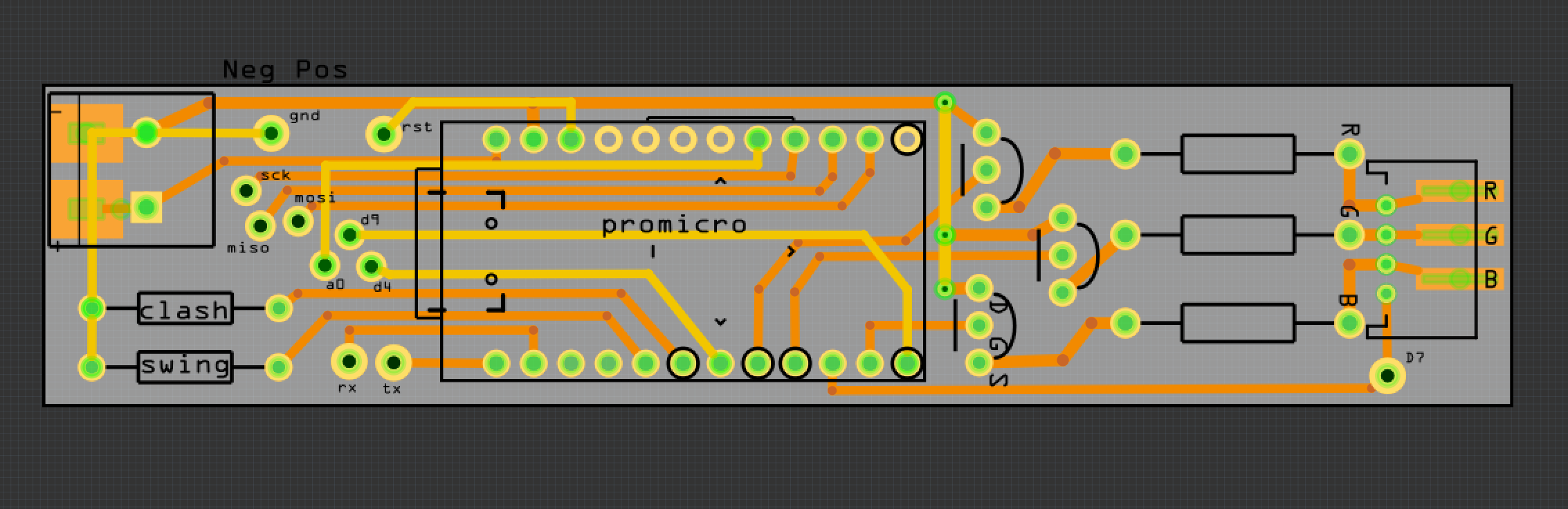
Sanity check of PCB
Hi - I've just designed this board to hookup an Arduino Pro micro clone and some mosfets and resistors to drive a cree RGB LED in a lightsaber project.
This is the first time I've done this, so wondered if anyone had any thoughts on the layout or design before I send it to be printed?
↧
Sanity check of PCB
While I don't see anything fatally wrong here (although our more experienced board folks may ), there are some issues. You look to have used vias (such as rst) for external connection points and they have odd drill sizes. I'd be tempted to replace them with either a single pin header (which has a standard footprint) or possibly a series of connectors unless there is a reason to have them in the pattern that they are. They look to be for external programming and thus an inline series of header pins would make connecting easier. Although it is a connector, on the pcb it is really just a pad and you can connect a wire to it rather than a header if you want. I'd be tempted to actually complete the schematic so you can see that the connections are as you expect as well (and probably breadboard it if you haven't to make sure it will work). You are using npn transistors rather than mosfets for instance, so you need to insure the leads match up (although from the silk screen notations you look to have done so). You also want to be using logic level drive mosfets, as standard ones typically want more than 5V of gate drive for full conduction. DRC (pcb view routing->design rules check) passes and the gerber output (file->export->for production->gerber looks fine in gerbv (you typically want to check the gerbers with a gerber viewer as that is what the board house will build the board from).
Peter
↧