Sorry Steel, it was you that made that part.
Vanepp linked about 20 upright parts in a post recently, but I can’t find it.
Sorry Steel, it was you that made that part.
Vanepp linked about 20 upright parts in a post recently, but I can’t find it.
Is this the same one.
If you search the forum for “top view” there are leds, TO220, ceramic cap and electrolitic caps available for use on perf board in breadboard view but not a lot, not an inductor as far as I know. There may be a small signal diode in upright as well (I made one a long time ago, don’t remember if upright was one of them)).
Peter
Do you mean a single pad part, because that is a VIA in the bin. You adjust size in Inspector.
There are too many words for it, because I tried standup, vertical, upright, and didn’t get much.
Actually I meant the one further up in this thread, I hadn’t remembered fixing that one (and don’t remember if it is offset leads, I think maybe not), but if it will do by all means use it :-). One or the other of them wanted a part with offset leads.
Peter
Yeah. you make so many parts dotted all over the place I worry they end up getting lost.
May I suggest that any of you that create a lot of parts and post them on the forum to start your own thread for just your parts.
I mean to clean them all up and submit them on github so they get it to the repository, I just haven’t gotten there yet …
Peter
You may suggest it… we have all thought about it… it’s a lot of work so we have never got around to it. There would be too many parts for a thread. Github would probably be better. They really need to be catalog in some kind of order so we know what we got and make them easy to find. I thought about it many times just never came up with a good was to organize them… and usually too busy doing something else.
Vanepp pretty much makes and fixes all the parts so it’s only his posts that have to be indexed, and because most are in Part Help they get scattered. Sure you can do a search, but some parts are similar to others but with different part numbers, and that may make a central repository/post quicker to find stuff. If I get bored I will make the post and link all the parts, because Peter has enough on his plate.
I was meaning ones own parts. Each time you post a part you would post it in your own thread and if you made the part because of another thread you would post a link in that thread to your part thread. This would allow you to update your parts without leaving a trail of broken files and also make it much easier to find your own parts when you want to link to it later when asked. Obviously putting them on github and making a pull request to have them added to the main arts repo is best but github can be intimidating and can actually deter people from helping.
I have been busy designing a control card for my CNC router with an Arduino Mega. As of yesterday I am unable to place or move existing traces. I can connect two parts with a trace but when I want to move the trace it jumps to the left upper corner of the pcb. Even when I want to place a new part on the pcb it jumps to the same corner.
When I take a example from the Fritzing library I can ad and move parts as I like.
I removed and installed the latest version. The design above is also made with the latest version.
…
…
Latest.
…
Please also attach any files that help explaining this problem
Post the sketch with the 7th button above.
What OS?
Sometimes shutting down FZ and restating fixes stuff, just save it first.
I am with @Old_Grey on this one. Post the fritzing sketch here and someone will have a look at it to see why this is happening (hopefully).
That’s what we do, it’s just that Van is so prolific at helping part requests in Part Help that it’s just way too much work creating the parts, upkeeping another tread in Part Submit, upkeeping revisions, and then doing it all again in Git.
We basically hope that people do a part search before requesting a part, and that kind-of finds stuff.
The OS is Windows 10 64Bit. Everything worked fine up until a sudden moment.
I will post the sketch this evening.
Did multiple restarts with no luck.
I’d like to say thank-you to all the members of the forum and the community who put in such hard work developing additional components and helping out us Newbies with our relentless and repetitive questions. It may not get said often enough, but we’re very grateful and we deeply appreciate the work you guys do.
Sadly it turns out I’m less skilled at modifying svg files than I thought I was. I’ll take another shot at it but thus far I seem to be missing something that is preventing my files from working correctly.
Thank you very much. I think that now I can begin the wiring.
I will see now if the W5500 is as the documentation that I have. The datasheet of the chip can be found on the next link: http://www.mt-system.ru/sites/default/files/documents/w5500_ds_v104e_140613.pdf
This is a hi and help plea from a total novice to everyone that can assist please.
Yes Vanepp, I think that you are about to read a post from someone that’s even more of a novice than you were!
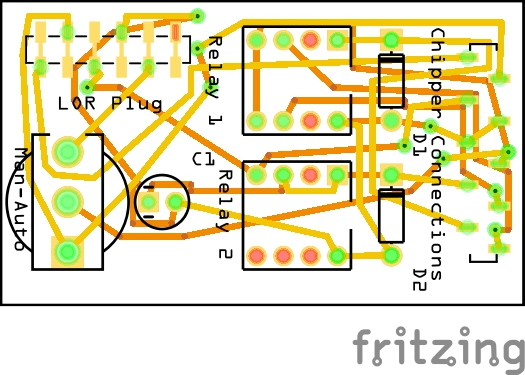
I’m in the process of trying to make a VERY simple pcb with 2 off 8 pin relays, 2 diodes, a capacitor, 5 off input wire connectors and 10 off output wire connectors!
I initially played with the Fritzing programme to see how easy it was to use and created a pcb and schematic that appeared to work using the parts already in the parts bin.
Now I want to make the same using the correct size relay pin spacing and connectors that I can use for “flying leads” to create a pcb I can use, but I’m not making any progress fast!
There are questions like what size is a “mil” for pin spacing and why can’t I edit an 8 pin relay for my own purposes etc?
I’ve tried to create the relay in Inkscape, but can’t open it in Fritzing and don’t have the computer skills to fathom out how to do it either.
I’ve read through some of your posts looking for assistance, but get totally confused with the terminology you all use.
This is where I’m at now really.
Attached is my initial try but I now need to create one that can take the relay that I want to use, which is an OMRON G2R-2 type 8 pin relay.
AntiStress Box2.fzz (24.6 KB)
Any assistance that you can provide would be very appreciated.
Cheers,
Rich