(post withdrawn by author, will be automatically deleted in 24 hours unless flagged)
↧
Need training on fritzing via team viewer, $40/hr PayPal
↧
Request - IRF520 MosFET module
So far, the result (as .PNG). Took me a while to understand how layers and such things work on Inkscape.
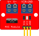
EDIT: Here is the .svg file IFR520_breadboard.fzbz (6.6 KB)
↧
↧
Request - IRF520 MosFET module
You can upload svg, at least that way we can see if something looks strange.
Did FZ accept it.
↧
Need training on fritzing via team viewer, $40/hr PayPal
I can do the pick and place with my homemade machine for you if you send me the boards and parts.
↧
Problem in running second time after installation in debian stretch
I am seeing the same problem with stretch x64 0.93b
I have tried installing from
http://fritzing.org/download/0.9.3b/linux-64bit/fritzing-0.9.3b.linux.AMD64.tar.bz2
I assume “running it” means executing the “install_fritzing.sh” in the tarball ?
I have tried that too.
I have also tried pulling the git repository and installing from there.
but there are a number of problems trying to do that.
There are hardcoded paths to /home/andre and unclear dependencies, such as for old versions of boost.
↧
↧
Problem in running second time after installation in debian stretch
Nope. Just Fritzing not install_fritzing.sh . The file called Fritzing is a binary file not a shell script.
↧
Searching for ST7735B - 128x160 TFT LCD Display part
I’ve seen the part in JPG captures of other Fritzing projects… but I’ve never seen the part for this display itself.
Did anyone ever create this part and upload to an archive here or on Github?
Can anyone provide a link here…?
Thanks
Mike
(1st post)
↧
Request - IRF520 MosFET module
Looks good, a few issues:
- scaled wrong
In Inkscape
ungroup everything to remove the transforms.
edit->select all
file->Document properties->resize page to content->Resize page to drawing or selection
to resize the origin to 0 (you should do this before regrouping on all svgs for fritzing)
note in the scale section of document properties that the scale is 0.01042 not 10.41667 which it should be to get the viewbox from the current viewbox 0 0 1.319322 1.0042583 to thte correct 0 0 1310.9322 1004.2583 which we are going to correct here.
with the entire drawing selected record the current size in px
x 0 y 0 w 125.712 h 117.648
edit->preferences->Behaviour->transoforms and make sure
scale stroke width is ticked (I normally untick this so Inkscape doesn’t change stroke widths on scaling but here it needs to be ticked for this to work).
now in doc properties change the scale to 10.4166 and click on the drawing. The image disappears (and unselects as well)
drag a selection rectangle around the top left corner and you get a selection (your image at the new scale)
edit-select all
the tool bar in px says
x 0.000 y 117.531 w 0.126 h 0.118
change that back to
x 0 y 0 w 125.712 h 117.648
and the drawing is now as it was except the viewbox is now
0 0 1309.4964 1225.4964
almost as it should be (I usually set the view box values to exactly match the height and width at this point).
- remove the label id from the Ifr540 text
in xml editor
select svg:text=“label” and change id from label to text3683 (chosen at random from another text string). label is special and Fritzing will replace it with the chip label from the fzp file which isn’t what is wanted here.
-
drag a select rectangle to enclose the three white connector dots on the IRF520 part and delete them. (this is optional, it won’t hurt anything to leave them there, but it reduces clutter when looking for connectors they are labeled as connectors in xml editor)
-
Change the tool bar units to in then click on each of connector0-6 and verify they pins are on .1 boundaries (which they are, good work!)
-
Set terminal IDs for the 3 .1 gold pins. At present with only a pin defined the conneciton will be to the center of the pin. While that is fine for the screw terminals of the headers we want the connetion to be at the bottom of the pin, not the middle. So duplicate a rectangle (I used “upperstripe” just below connector2pin)
That created rect994 at the bottom of xml edior
in the tool bar change height and width to .01in (10 thou)
in xml editor select the transform (scale 1,-1) and delete the (scale 1,-1) (replace it with blanks) and hit set
the transform is removed and the rectangle moves up in the drawing. Still in xml editor
change height and width to 10
change style to fill:none;stroke-width:0
this creates an invisible rectangle which will become our terminal so now change id to
connector0terminal and set it to make the change. We now have the terminal but it is in the wrong place, so go to the tool bar and set x to 0.8 (from .210) which moves it to the x position of connector0pin-1 (which is the incorrect name, so in xml editor change the id to connector0pin and set it). Set y to 0 which moves it to the approximate end of the terminal where we want it. Repeat this step (by duplicating connector0terminal and changing x by .1 higher to move it to the next pin and renaming it connector1terminal)
Now we have the 3 terminals we need to align them properly (note, if you can make it work which I usually can’t this is easier in parts editor).
I notice that the pins all have a transform (scale -1) since I dislike transforms (as in my view should you) I removed them by replacing them with blanks in xml editor
connector2pin x 0.807 y 0.010
remove transform
x -0.839 y 2.341
change back to
x 0.807 y 0.010 via the tool bar and the pin is in the right place without the transform.
and it is back in position without the transform.
repeat for 1 and 2
Now with the pins in the proper place and without transforms move the terminals in to postion
because the pin is .032 wide and the teminal is only .01 wide, the x coord is a little larger to center the terminal on the pin. In my case I used x 0.817 instead of the 0.807 for the pin and .01 for y. The next two pins are .1 larger in x, so repeat twice more to get the pins correctly positioned.
Almost done, one last thing: set the layerId to breadboard.
edit->select all
object group
change the id of the resulting group to breadboard
and we are done.
file>save as->plain svg
save replace then exit Inkscape without saving (it will want to replace the plain svg with Inkscape svg which we don’t want.)
Now rename
IFR520_breadboard.svg
to
IFR520_breadboard.fzpz
because the forum sometimes has problems uploading svg files. When you download this change the name back to .svg and you are away. Hopefully the formatting in this is ok …
So all that said here is my corrected svg file (named .fzpz):
IFR520_breadboard.fzpz (51.7 KB)
change it back to svg to display it. Note it will have px in the font-sizes as I didn’t post process it, and the terminalId defintions will need to be added either via parts editor (or if it is me via a text editor  ) to the fzp file for the part. I’ll probably be out for the rest of the day so response may be delayed.
Peter
↧
Searching for ST7735B - 128x160 TFT LCD Display part
Did you search Google. Follow those images and look for .fzpz or .fzz or .fzb. It could also be a part in someone’s big bin, like Adafruit.
Do you have link to a datasheet so we can see how hard it is to make.
↧
↧
Problem in running second time after installation in debian stretch
The head code has an updated set of install scripts (although I think still hard coded paths). I think they may be intended for the machine that creates releases rather than the general public but I’m not sure. I’m not aware of any documentation on the install scripts that may tell us.
Peter
↧
Searching for ST7735B - 128x160 TFT LCD Display part
From a google search with the term “fritzing part st7735b” it appears to be in the adafruit fritzing library on github. That library isn’t loaded in to fritzing by default you need to download the bin from github and load it in to fritzing.
Peter
↧
LinkIt One Development Board
It looks like an green UNO from the USB side to the 2 holes on the notch side but extended 0.6", so I did that and removed some nodes. Anybody want to make it pretty.
As usual change the .fzz to .svg. How are people directly posting svg images here.
LinkIt One.fzz (224.8 KB)
EDIT - New upload because I forgot to change the headers to yellow.


I notice Seeedstudio makes it, did anyone look there for the part.
↧
LinkIt One Development Board
You just upload it like you would an fzz file. If the image appears tiny or invisible it is becasue the size needs to be changed. In the data the forum generates around the upload it will have the dimensions and often it is only 1x1 which is 1pixel by 1pixel. You just scale up the numbers to something around 300. In this case it is 3x2 which i scaled up to 300x200

This is what it looks like after upload.
This is after I changed the dimensions.
↧
↧
LinkIt One Development Board
I thought I could see a tiny green box when I tried.
If no one wants to fix it up I’ll try latter, it’s just that I’m not good a text and logo so I might have to leave them off.
↧
LinkIt One Development Board
Yes, it’s not there nor on the media one site that I could see although there was apparently one at some point (perhaps not public though).
Peter
↧
Select PTC fuse
I have this Arduino based circuit(Speeduino) running my car’s EFI, and a couple of days ago it blew the 32 and 16 mil traces. I’m thinking it blew because it was running on the car’s 12V and I had just plugged the laptop into the common 12V cigarette lighter. Both used to run on the same 12V, it’s only the datalogger in the controller program(TunerSudio) would freeze. I was testing why the traces blew on the bench using my DIY PS, but when I plugged my laptop into the same 240V as the PS the USB chip of the MEGA2560 went up in smoke. It kind-of looks like the USB protection in the laptop is shorted and letting it ground through the laptop now.
I now want to isolate everything from the high current MOSFETs so I’m leaving the 16mil cut, running a wire from that trace to the Arduino side of the 32mil trace, and putting a PTC fuse across the 32mil break. I want to select a PTC low enough that the MEGA won’t fry, but not too low that the car might stop unexpectly. When I plug the Speedy into a USB doctor meter is shows a sudden surge to 1.5-1.8A and quickly drops to 200ma, but across the 32mil broken trace I’m only getting 30ma. What would be a good size PTC?

This is the original sketch without the mods -323-v3.6-Ver2.fzz (419.1 KB)
I will be using a USB isolator from now on, and might even take the laptop apart to see what’s happening, but the extra protection shouldn’t hurt.
↧
Greetings to All!
Greetings for the day!!! I am a software engineering with a company that manufactures and exports Science lab instruments and equipment. I am looking forward to lots of quality discussions here on Fritzing
↧
↧
Connecting raspberry with arduino via usb
I want to connect my raspberry Pi with arduino using the usb cable in the breadboard workspace How can I do it thank you
↧
DC Motor with two-phase encoder
thank you I really needed it 
↧
Changing the color of LED
Howdy all?
I have just started using Fritzing and I was wondering how can I change the color of the standard LED that comes with Fritzing?
I have searched everywhere and could not find anywhere how I can do that.
Any help is greatly appreciated.
Thanks!
↧