You can just click on 1 PCB at a time and run the DRC.
You also have to do the same thing when you export.
You can just click on 1 PCB at a time and run the DRC.
You also have to do the same thing when you export.
I tried that (because it said something like that) but couldn’t make it work. Then I gave up  . Maybe I’ll poke some more later.
Peter
I just tried it and it worked. I clicked the grey part of the PCB.
OK here is a part. Even more than usual, please check the footprint against a real part before committing to making a board. I think the footprint is correct but the data sheet is a little unclear. It also isn’t clear what ground does, but it is there, so I included it (I assume it grounds the metal case perhaps). Breadboard shows the part on a breakout board because the pin layout doesn’t suit standard breadboard practices.
AlpsJoystick.fzpz (10.0 KB)
Peter
I didn’t use the DRC check for my board,
and there are many pads/via or holes overlap by purpose
it is not the first design I didn’t use DRC check, I probably never followed the DRC rules 
yeah, sometimes there are unintentional overlaps,
but I got use to it, checking the gerber export also did my own DRC job.
the three board in the files work as needed and can play the POV effect photoes in the PJRC project post.
Yep, when I click on the grey of the pcb as Old_Grey suggested and then select Routing->Design Rules Check (DRC) Fritzing is unhappy about the routing. This may or may not indicate anything because as I recall these leds are narrow spacing, but it would be good to be sure before trying to cut boards. That said, the gerber output doesn’t look too bad, so it may just be that DRC is being too strict. The board on the bottom right looks to have the top trace outside the board boundary and will likely be truncated at the board edge by a bit.
Peter
I can’t remember the tolerance FZ deems as too close, maybe 0.01", but I think PCB houses are 0.006". Better check to be sure.
You can click on the fault in the DRC box and it will show red on the PCB, then you decide if you let it go.
pulling wires to-and-from the small pads often point to neibor pads, due to the close and small size.
I use copper text “_” instead of traces for easier copy and paste, that is a tip for 80 small LEDs,
and probably that is one of the thing that DRC check cannot accept, but worked for me.
Yes they are… I already said… Some of parts I had to edit…
Because, in BB view, Every terminals look same and they are all in 2.54mm pitch…
And in PCB view the silkscreen shows their sizes, those hardly match my actual parts…
So, I made them for easy to use and detect the direction easily on PCB…
That’s why, I made more of them with same pitch, but different Silkscreen…
Like Old_Grey I’m to lazy to go through all the parts, but I did look over 01.transformer 1 and have a few comments for improvement:
in all cases the svgs aren’t at the suggested scale so I rescaled all of them. Makes no visual difference but makes part checking easier.
Breadboard
rescale and renumber connector 5 to connector 4 to remain in sequence. This is important because the labels will display wrong if the pins are out of sequence. Otherwise nothing that needed changing.
pcb:
rescale, then change all the pads to have a stroke width of 20 thou (the recommended size). Adjust the radius on the pads to produce a 0.035 in hole (it is currently a bit bigger than 0.028 which will typically round up to the next higher drill size). Change connector5 and 6 to 4 and 5 to remain in sequence. Change pin to pad on 5 and 6 to match the rest of the pins.
schematic:
First in Inkscape did Edit->select all then resize page to content as the drawing is beyond the view box and will thus truncate. You should always do this just before saving a svg file to make sure the viewbox is correct. Then rescale the drawing. The two bottom pins on the transformer are not aligned to the .1 grid:
while the grid doesn’t show very well in this, your part (on the right) has the pins connecting to j6 and j7 half way between two grid lines. Corrected that to properly align the pins to the grid. First I went through and changed the stroke widths on all the terminal lines to be 10 thou (because connecting lines in schematic art 10 thou and it is desirable the two match). Changed pins 5 and 6 to 4 and 5 to maintain sequence.
fzp file
Change pins 5 and 6 to 4 and 5 to match the svgs and changed the pcb layer for pins 5 and 6 from pin to pad.
Ran the part through the FrtizingCheckPart.py script to flag any errors (there are none) and to clean the trailing px on font-size and inline the style commands (Fritzing doesn’t always support CSS, so inline is safer). Rezip the result to produce this new part (so you can load your original along side this to see the changes):
01_Transformer_improved.fzpz (6.3 KB)
Hope this helps …
Peter
There are many bugs sometimes which can easily be resolved and you can contact the admin about the issue like I contacted the admin of the site https://epsonsupports.net/blog/fix-reset-ink-cartridge-epson/ where there was login issue.
This one was a dream, excellent documentation. As always check the pcb footprint before ordering boards, but I’m fairly confident it is correct.
Sony_Spresense.fzpz (22.3 KB)
Peter
Thanks for the improvement…
The transformer is the first part I created, there was no ferrite core Tr available.
It took me about a month to understand the editing rules in every view.
The thickness in schem was 5x at first, I recently change it…
Also, thanks for the hole size info…
But, I did not understand, why you put two pins with same number (pin 4)…
There are total 6 pin in that part…
As I wrote earlier, there are 3 additional busses. The pin 18 is shared with sda pin and the pin 19 with scl pin. The same is right for two ioref pins of the power and ioref connectors. You can see all the busses in my part, either in the breadboard view or in the HiFive1.fzp file.
 <buses>
  <bus id="5v">
   <nodeMember connectorId="connector87"/>
   <nodeMember connectorId="connector92"/>
  </bus>
  <bus id="gnd">
   <nodeMember connectorId="connector57"/>
   <nodeMember connectorId="connector88"/>
   <nodeMember connectorId="connector89"/>
  </bus>
  <bus id="18/sda">
   <nodeMember connectorId="connector4"/>
   <nodeMember connectorId="connector59"/>
  </bus>
  <bus id="19/scl">
   <nodeMember connectorId="connector5"/>
   <nodeMember connectorId="connector60"/>
  </bus>
  <bus id="3v3">
   <nodeMember connectorId="connector86"/>
   <nodeMember connectorId="connector94"/>
  </bus>
  <bus id="iref">
   <nodeMember connectorId="connector84"/>
   <nodeMember connectorId="connector93"/>
  </bus>
 </buses>
Michael
Thanks a lot, I know you done a lot and it is a bit rude of me to ask you for another component, but the Sony Spresense comes with an expansion board, image below. It would be quite essential for schematics with the Sony Spresense board. The Spresense main board clicks on to it.
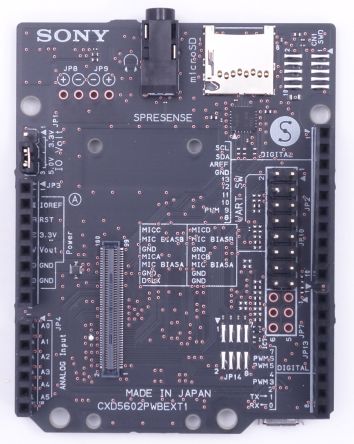
Sorry for the continuous requests,
Andrei.
Yes there are indeed 6 pins. In the outside world they are usually numbered 1 to 6, but in Fritzing they are numbered 0 to 5 (something that confuses a lot of people ). Your original part skipped pin 4 to define pins 5 and 6. That is a problem because Fritzing for reasons I don’t yet understand (because I haven’t dug in to the source that far yet) predicts what the next pin number will be when displaying labels when you hover over a pin. If the pins are out of sequence it will display the wrong label for the out of sequence pin which is an error. For this part that probably doesn’t matter, but the part checking script detects out of sequence numbers and complains (and it is incorrect as noted).
Peter
Ah, good I’m just used to people not understanding what a bus in Fritzing really means but you look to be on top of it!
Peter
Not a problem, this should be easy enough to do (and needs the first part in order to work anyway). I did wonder if you wanted both of them .
Peter
Okay, I checked the svg file. Now I get it…
The problem was in the pin name in the svg file…
I noticed that from the beginning of editing parts… That’s not confusing to me…
But it get confusing when I was creating new parts…
When I create a new part, In editing window, I always remove all the reference part’s connectors, and then I put my pin number in “number of connection”…
And the Fritzing unfortunately creates new number of pins from "connector1"
And for auto pin connection I number my pins from “connector1pin”…
Anyway, If you check my “Pro-mini-MU”… then you’ll get Huge number of errors… 
(I just checked the svg…!!!  )
)
Also, I’m going create a topic about some Fritzing problems, that should be fixed by now, don’t know why this amazing software did not updated after 2016…!!!
That’s fairly easy. Fritzing was originally a funded University research project. Then the funding ran out and it converted to open source with the hope that donations would fund the project. That hasn’t happened and development has died and probably most of the developers have moved on. I have been trying for about the last 2 years (with no particular success so far) to get a development environment up and running. At present I’m working on the parts check script to get it to remove tspans from the parts in core. That is because the current version of Qt (the framework Fritzing runs on top of) dies if it hits a tspan. Once the handful of parts in core are fixed then maybe I can get development going although last I checked (last summer sometime) the 32 bit Windows version of Qt was not installable and it is required to make a release. The reason for making a release is that at present parts update is broken on at least Windows 7 due to it using TLS1.1 which github no longer supports. If you are willing and able to help start development up again the help would be greatly appreciated. I need to find someone capable of bringing up a development environment on the Mac (I can do Linux and Windows but don’t have a Mac) as well. There is a thread on my progress (mostly the lack of it) in the developers section of the forum. It hasn’t been updated in a long time though.
Peter

