Thanks for your reply.I will try it.
↧
Empty rectangle
↧
Empty rectangle
If you can’t figure it out, feel free to upload the .fzz file for your sketch and ask for help. Someone here can likely help given the files to look at.
Peter
↧
↧
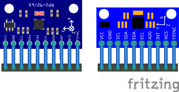
New part for MPU-9250
Hi there! First time poster and all that.
I have one of those breakout boards and used it to learn how to make parts for fritzing. I know my measurements aren’t 100%, but the pcb spacing should be correct as it is standard 0.1" spacing. I will be making a v2 that is much more accurate sometime soon.
Please check it out and let me know what you think.
Thanks
Randy
MPU 9250 Breakout.fzpz (10.0 KB)
↧
Empty rectangle
… good timing…
When I did the PCB (vanepp’s reference to my post), I used several drawing App’s to determine usability with respect to ‘my’ needs and desire to make the process painless.
One of the Apps is call ‘GravitDesigner’. It had flaws and the user interface is much like a typical drawing app but carries along with it the usual need to learn it. I prefer the user interface of EZDraw but can live with Gravit.
I was pleased to see Gravit was updated and the bug’s fixed. So, I tried it yesterday and am a happy camper 
Sure, it took me some minutes to go through their tutorials BUT, it was worth it!.
The Best Part about using it is the ‘Layer’ panel which eliminates the need of messing with XML (especially in InkScape).
I discovered that I can drag and drop the Layer’s label into another Layer to yield Sub-Layer’s and rename as needed.
Plus, I discovered that setting an element to a Symbol will make it a sub-layer and sets the ID to the name of the label. Seems to work great for the PCB’s that I make.
If it works out (will try it today), making ‘Parts’ will be easier than using Inkscape and editing the XML (for Pin connections…etc). Will follow-up and post to the reference post…
Two images attached:
- Collage of Gerber outputs from Fritzing. The Copper colored item is the result in CopperCam - the app I use to generate Gcode for CNC machining PCB’s. The Black dot is a ‘Hole’, using the ‘hole’ part in Fritzing.
- Gravits user window (for Mac but, I imagine their Windows version is much the same).


↧
PCB Custom Shapes, Cutouts, Holes… Simplified
UPDATE:
Brief follow-up…
I used several drawing App’s to determine usability with respect to ‘my’ needs and desire to make the process painless.
One of the Apps is call ‘GravitDesigner’. It had flaws and the user interface is much like a typical drawing app but carries along with it the usual need to learn it. I prefer the user interface of EZDraw but can live with Gravit.
I was pleased to see Gravit was updated and the bug’s fixed. So, I tried it yesterday and am a happy camper
Sure, it took me some minutes to go through their tutorials BUT, it was worth it!.
The Best Part about using it is the ‘Layer’ panel which eliminates the need of messing with XML (especially in InkScape).
I discovered that I can drag and drop the Layer’s label into another Layer to yield Sub-Layer’s and rename as needed.
Plus, I discovered that setting an element to a Symbol will make it a sub-layer and sets the ID to the name of the label. Seems to work great for the PCB’s that I make.
If it works out (will try it today), making ‘Parts’ will be easier than using Inkscape and editing the XML (for Pin connections…etc). Will follow-up and post to the reference post…
Two images attached:
- Collage of Gerber outputs from Fritzing. The Copper colored item is the result in CopperCam - the app I use to generate Gcode for CNC machining PCB’s. The Black dot is a ‘Hole’, using the ‘hole’ part in Fritzing.
- Gravits user window (for Mac but, I imagine their Windows version is much the same)

↧
↧
New part for MPU-9250
Not at all bad, a few problems though. As noted as I replaced the part above I find I have two of these and calipered them and modified the part. Looks like you have a different board because mine is bigger:
The breadboard svg is missing the layerId breadkboard group. The only thing I know that breaks is svg / pdf export. Your part won’t show up in such an export.
schematic has most of the problems:

The wires are connecting in the middle of the pin because the terminalId is missing in the schematic svg. That is typically a 10 thou square at the end of the pin (parts editor will add it for you if you are using parts editor, I rarely do though preferiring to eedit the files directly). I usually prefer to make schematic match breadboard to make debugging easier ( I can see where a pin goes in schematic without searching for the pin number), but either way is fine. Your way actually uses less space in schematic which i s a good thing on complex sketches.
pcb is file except it lacks the board outline so you can see where the board is sitting on the pcb so you don’t try and place components there. Note on my board the mounting holes are shown on silkscreen but not drilled. That way if the user wants mounting holes they can drag a hole from core parts over the silkscreen hole, and if they don’t want mounting holes they can route traces through that space.

finally the test sketch (which I used to make sure I hadn’t broken my part with the changes). The 45 degree connections in schematic catch terminalId problems. The check script complained about the lack of termanalIds in schematic but will be perfect;y happy with a terminalId going to the wrong pin (because it is there). This catches that case.
Peter
↧
Empty rectangle
GravitDesigner looks interesting, I’ll probably give it a try (having just been bit by Inkscape yet again). At a quick look it wasn’t clear to me if it is o[en source or a free version of a commercial product or not (like Eagle). I’d rather have open source so it doen’t get sold (again like Eagle  ) and potentially killed. Thanks for the heads up!
Peter
↧
Empty rectangle
Peter, the good news is that Gravit was already sold (to Corel, the long-standing drawing folks).
I’m using the Free version (downloaded from Apple’ store) but, here’s the link to Gravit, clicking the download button… don’t see any cost info…)
I very quickly made a new Part with it (not yet finished) but, it was smooth and twice as fast (versus Inkscape) and without the drudgery. Screenshot attached showing the Layer panel.
The only shortcoming (that affects me) so far is the Scale between Gravit and Fritzing for a PCB (will know about scale for Parts after I finish the part I started, though I imagine a similar mention). But, Scaling for Fritzing was a breeze - simply multiplied by 1.25 ( which is, 90/72 = 1.25).

FOLLOW-UP…. Was curious if difference between version downloaded from Apple and Gravit’s site. ‘Yes’, there is a difference - the Apple store download has some left-over bugs but, the one downloaded from Gravit doesn’t (in particular, the “Recent” file opening. Don’t yet know about other issues.
But, downloading and installing it (from Gravit) did not cost any money or required login’s. I have a internet blocker and no issues. It’s a Stand-Alone version… I refuse to use the Cloud!
Yes, the version downloaded from Gravit’s site is updated and runs great as stand-alone (on Mac). Recent-files bug is fixed.
↧
Empty rectangle
I’ll download a copy and try it out. Inkscape just bit me yet again. Possibly because I typed some hot key sequence it decided that copy/past of parts between different Inkscape windows should occur as poor quality bit maps instead of xml. Yesterday (possibly for the same reason) it was doing all moves via translates. In both cases copying the initial preferences.xml file back in to preferences.xml fixed it, which is why I 'm thinking it is me mistyping and tripping hot keys. I maybe should try and disable all the hot keys I don’t actually use (which is most of them). While I’ll look at Gravit, part of the reason I stay with Inkscape (as opposed to a paid copy of Corel Draw which was recommended to me) is so that someone knows Inkscape to support folks here using it. I wouldn’t mind working on fixing the Inkscape bugs, except for time, and I have heard they aren’t real receptive to patches from folks not in their inner circle (which I can sympathise with actually ).
Peter
↧
↧
1 of 2 nets routed
Hi. Newbie question.
I’m thinking about to produce LED Blinking.
Then I have created using the Breadboard view. However,
I notice a message on the breadboard view’s status bar saying “1 of 2 nets routed - 1 connection still to be routed”.
When I click on the message I get the following message “There are no unrouted connections in this view”.
How do I find the unrouted connection mentioned in the first message?
Is there an unrouted message?
Here is my file:
Sketch .fzz (3.4 KB)
Thanks,
Kimura.
↧
1 of 2 nets routed
When I loaded your sketch in Fritzing 0.9.3b on Win7 it says breadboard is routing completed which looks to be correct (all the connection points are green). There are unrouted connections in schematic, and in addition the grid was set to an odd value (which may just be me ). To check in schematic click on view->set grid size and if it is something other than .1 in, click the restore default button (which will set it back to 0.1) and click ok. You then need to move all your parts and connections so they snap to the grid correctly. Normally the “still to be routed” message means you have connections that are still red (even though they look connected if they are red, they are not and you need to move them til they turn green). If that doesn’t fix your problem, post again, because this may also be database corruption on your machine and there is a different cure for that if it is present.
Peter
↧
Would love some help/feedback
I’m so sorry Peter, if you’re still around, I have one more question.
After reading this I looked more closely and it seems I have kept the Stepper motor driver Logic and VMOT ground pins separate, but not sure if they’re correctly separated…It’s kind of hard to tell which of the Capacitors connected to the Voltage regulator are the 12v or 5v GND. Or does it not matter as long as they’re just separate?
Meaning as long as I keep one capacitor all connected to 12V GND pins and the other Cap all connected to 5v GND pins, it doesn’t actually matter which of those it is right?
Hopefully Im making sense! haha
↧
Would love some help/feedback
Assuming your board looks the same, it would be better to route the ground furthest to the left (the logic ground) directly to the ground on the micro, looking at it moving the ground on the 5V filter capacitor would be a good bet too. As well the i2 input wants to be to logic ground not motor ground (which may get high enough to change the logic level with bad results.) I deleted the ground fill to make the routing more obvious:
MP6500_blinds_PCB_Copper_Bottom2.fzz (53.1 KB)
The basic idea is the logic ground and filter cap are completely separate from the motor current path (which they aren’t at present). In the layout above all of the 5V filter cap ground, the logic ground from the motor controller and the ground to the 5V filter capacitor all join at the microprocessor ground pin (all of them are low current.) The motor current goes on a different path where voltage drops won’t affect the logic signal levels. It probably won’t matter in this case but would with a higher current motor. Did you get the ground seed issue worked out?
Peter
↧
↧
Empty rectangle
I got around to finishing a test Part - ran into a Hiccup that drove me nuts.
Posted it at Gravits forum, received a quick answer that fixed it! Not really a bug but an added item to the Element’s Tag.
They already flagged it - until it’s taken care of, Editing the XML is needed.
Simply delete this “vector-effect=“non-scaling-stroke” from the Elements and the problem is gone.
I’ll finish up the test part (so you, Peter) can run it through your test code. May be a day or two as I have some things to do…
↧
MRFC522 parts Not found
Hello,
I am very new member of this forum. I was trying to make project with MRFC522. But I cant find this part in software. I got some for RFID but I am looking for mifare one. The one with RFID does not match PIN outs.
Can anybody help on this?
↧
MRFC522 parts Not found
A google search for “fritzing part MRFC522” turns up one in a project:
http://fritzing.org/projects/control-acess-rfid-rc522
If you download the .fzz file the MRFC522 part should be in the temp parts bin and can be exported by right clicking on the part then selecting export part. That gives you an fzpz file which you can load in to fritzing to load (and then reuse) the part. There is also a part available in a github repository (which may be the same part in the project):
I haven’t looked at either part, so if they don’t work or aren’t suitable, post again and I’ll have a look at fixing one or the other or finding a third one.
Peter
↧
Empty rectangle
Sounds good, I haven’t yet gotten to downloading this, I’m trying to finish up fixing the part template files on the web site (which are horribly broken, dimensions in px with the original Illustrator 72dpi scale, which loads at the wrong scale in Inkscape, no wonder people were having trouble with it!) Once that is done I’ll see if I can get someone to replace the file on the web site. In between beating on the development Environment. I have copies for Win64 and Win32 on Win 7 pro running and am now working on Win10. Then comes the boring part of writing it all up so other people can do it too.
Edit:
If you have a chance, see if it is better than Inkscape at removing transforms from documents. I can’t make Inkscape do it at all (even with the apply transforms extension), but it should be possible to do I think. It should improve performance although I’m not sure it will be significant.
Peter
↧
↧
MRFC522 parts Not found
Seems similar. Thanks a lot. Will get back you as soon as I test the whole project.
Thanks once again.
↧
1 of 2 nets routed
thanks I’ve tried but not fixed.
When I loaded this sketch in Fritzing 0.9.3b on Win10 (fritzing.0.9.3b.64.pc.zip) ,
the breadboard view looks to be collect (all points are green.) , and
schematic view’s probrem is resolved.
However,
breadboard view’s status bar is saying “1 of 2 nets routed - 1 connection still to be routed” yet.
It would be appreciated if you could assist to track down the problem.
↧
MRFC522 parts Not found
Parts from the net are of varying quality, some are excellent, some are poor quality or non functional because part creation is hard, so if doesn’t work out feel free to post, I can usually fix up broken parts.
Peter
↧