Quantcast
Channel: fritzing forum - Latest posts
Viewing all 32411 articles
Browse latest View live

Conception de 2 circuits imprimés avec capteurs à effet hall , et une carte arduino , pour un accordéon

$
0
0

I agree, while Fritzing is a lot easier to use that the other EDA programs it is still fairly complex. I think the most likely problem you are having is selection (correct me if I am wrong here). In order to change the position of something you must have it selected which isn’t always the easiest thing to do (because Fritzing sometimes selects something other than what you expect). Assuming you want to change U49 (the end sensor), first you need to select it so Inspector recognizes it. Here is an image with U41 (off screen) selected and thus U49 not selected:

Unselected

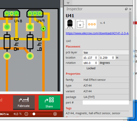
U49 looks just like U48 next to it and Inspector says “U41” to indicate U41 is selected. To select U49 you need to click on it til it looks like this and comes up in Inspector as U49:

Selected

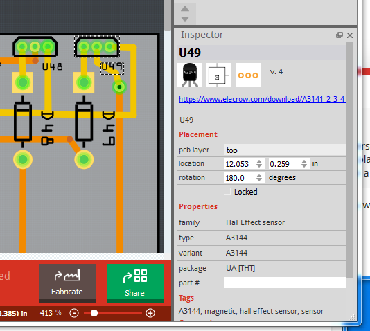
Notice the dashed line around U49, that is the selected indication (It could also select one of the traces nearby, in which case that would have the dotted line around it), as well Inspector now shows U49 is selected. At this point you can either type numbers over the X and y coordinate values, or use the up and down arrow beside the numbers to increment them and thus move the part. You likely only want to move in X (horizontally) so you want the left most box in location.

Peter


Where to find this "Stereo Audio Amplifier board" design!

$
0
0

Fritzing%20Audio%20Amplifier%20Board

“Stereo Audio Amplifier Board”
I want to download this module as .fzz but I never found it.
Anyone have any idea where I can add this board to Fritzing file!
what is the specific name for it?

Where to find this "Stereo Audio Amplifier board" design!

$
0
0

A google search for “fritzing part Stereo Audio Amplifier Board” (under the images tab) says this is a PAM8403 6W STEREO AMPLIFIER. A google search for that indicates a part is available on github:

fritzing part PAM8403 6W STEREO AMPLIFIER

first hit:

I have no idea if the part is any good or not, but you should start there. If it doesn’t work, post again and I (or someone else) will have a look at the part.

Peter

Where to find this "Stereo Audio Amplifier board" design!

PLCC 84 socket part?

$
0
0

OK this should do the job. As always verify the footprint matches an actual part (I used a milmaz data sheet as they had a full description of the recommended foot print plus pin numbers on the layout, neither of which your data sheet has.)

W65C256S.fzpz (14.3 KB)

Unrelated to the part, if you want to breadboard this and have a wire wrap tool (after my scope, my best investment ever :slight_smile: ) Using 30 pin SIP wirewrap sockets (used to be available from electronix express), they would fit the pins of cheap import plcc sockets available locally (and probably at least the milmax ones too). I have a Z380 in plcc on a piece of perfboard with 64K of ram all wire wrapped.

Peter

Como hacer un rele

$
0
0

Hola alguien sabe como hacer un relay - quiero hacer un circuito donde tenga una entrada de 220 - 240 en este circuito ira un arduino - un relay y a futuro poder agregar mas relay - alguien que me enseñe o ayude :confused:

Conception de 2 circuits imprimés avec capteurs à effet hall , et une carte arduino , pour un accordéon

$
0
0

Hello peter,
I understand how to select a U49 component for example, I sufficiently magnified the view is I click that it’s not difficult then I know very well select the sensor is change the values in mm however the software changes the value that I have worn! after moving to another component example U 47 I do not understand why !. I annotated the file fzz with my values in mm between each sensor taking as axis the pin 2 of each sensor and knowing that the magnet will straddle the corresponding rod in the same axis. I am going to install iphotodraw for you put more specific informations. thank you

Advice needed for a LED Strip Fuse Box

$
0
0

Hello,
i’m currently working on a Fuse Box for SK6812 LED Strips, since all of the 15m Strips would at full brightness end up using 38,4A i’m going to seperaten them into 2m pieces each which and end up with 4.8A per Trace and Wire.

My Idea behind the Box is that i’m going to use a Wemos D1 mini which monitors the Voltage and current of the 8 LED Strip Lines and shuts down the line as soon as it hits 4.8A with a Relay the Fuses behind it, are just a Fallback and Fast Blow 5A Fuses.

Also i tryed to at least do all of the traces that are Ground to the Bottom of the PCB to do a mass fill later.

I think most of the traces should’nt be a Problem but i’m still running into 2 issues.

  1. I don’t know how i’m going to measure the 5A since the limit of the INA219 is 3,2A i did a sketch using a ATiny and a ACS712T but that one is limited to current measure and i don’t know if i can just put one of the ATiny Pins on the Phase or not.

  2. I’m still confused because originally i wanted to use SSR Relays to shut down the Lines but now i have read somewhere that it’s not so easy if you are using DC Current like i do. And Heat will be a big Problem… So i’m a bit lost there now.

Everything else should be straight forward the 74hct245 is a logic level shifter to stabilize the DIN on the Strips.

PCF8574 is a bus expander to control the relays and the TCA9548A is a i2c expander which was orginally for the INAs.

I also asked the some questions on the fastLED and Teensy forum but… Someone i want get any help there.

Fuse Box.fzz (246.4 KB)
currentmeter.fzz (7.0 KB)


Advice needed for a LED Strip Fuse Box

$
0
0

The Fuse Box sketch is missing part PCF8574. If it’s in your sketch it’s probably faulty, so maybe upload it here so we can see if it has a problem.

Fritzing don't save scheme

$
0
0

So when I chose “Save as” and chose filename for project, button what should be “save” is named “open”. And I can only open new folders as long i reach finish of directory and in last click “save” window disappear. The same for “Save”. When I exit without save and fritzing ask me if I want to save and I chose yes. It is the same. Can’t save scheme :frowning:

Linux mint 19.1 Tessa, fritzing from repository.

Conception de 2 circuits imprimés avec capteurs à effet hall , et une carte arduino , pour un accordéon

$
0
0

Ah! Easy to fix. You are likely being bit by snap to grid (which is enabled by default). Click View, then untick Align to grid (4th icon down).That should fix the problem. I have the grid size set to .1 mm (instead of the default 2.54mm) which will do the same thing as disabling snap to grid. I’m just adding a second connector to deal with the two connections to 1 mega pin and will post the fully routed boards for both sides.

Peter

Advice needed for a LED Strip Fuse Box

Como hacer un rele

$
0
0

A google search for “fritzing 220v relay” turns up a bunch of projects using relays, pick one.

via google translate

Una búsqueda en Google de “fritzing 220v relay” muestra un montón de proyectos que utilizan relés, elige uno.

Peter

Fritzing don't save scheme

$
0
0

Sounds like the install from the repository is broken. I’d recommend trying the install from the Fritzing site by downloading the tar file and untarring it. That works fine on Ubuntu 18.04. If you don’'t have any sketches or custom parts you could try removing the user directories (Fritzing will replace them) in case it is database corruption. On linus they should be:

~/Documents/Fritzing/parts
~/.config/Fritzing

You can also just rename the two of them to keep the current copies and move them back if there is no change.

Peter

Advice needed for a LED Strip Fuse Box

$
0
0

The current capability of the INA219 is set by the size of the shunt resistor. Changing the value of the shunt resistor changes the maximum current detectable. That said I would use a INA3221 which has an internal A/D and gives a digital output such as this:

There is a hack (involving cutting traces) on the net to make the inputs take 3 different voltages but you likely don’t need it. You may need to reduce the value of the shunt resistor (currently .1 ohm) to get 5A full scale, you would have to check the data sheet to see what full scale is at present. As to your relays I’d use power MOSFETs such as this:

If you don’t want the module, you can use a logic level power MOSFET instead (and optoisolate it if you choose). You do need to make sure you drive the MOSFET fully on (thus the logic level gate drive) to avoid burning it out.

Peter


Advice needed for a LED Strip Fuse Box

$
0
0

The thing is that the Resistor on the INA is an SMD Part which would be quite hard to replace without the nessecarry tools (that i don’t have) this was also the reason why i preferred THT and DIP over SMD and SOP Parts on my Board, because it would be easier to solder and replace. Even if the whole PCB get’s a big bigger than.

And yes i also thought about the Mosfet with a logic gate but was still confused with the explanation of how to choose the right one for it, because of the VDD, VGS and other Values that they have. So if i did a mistake there all of the current would end up in Heat. But of course a direct solution would be better than a another pcb on the board. I also don’t get why there are 2 mosfet on the board should’nt one be enough?

Advice needed for a LED Strip Fuse Box

$
0
0

You need to find a logic level MOSFET (i.e. VGS for full on is ~2.5V not 8 or 10V like a non logic level MOSFET) and fairly high current so RDSON is low (and it thus doesn’t heat up much due to internal resistance). There are lots around.

2 separate channels on 1 board.

Peter

PLCC 84 socket part?

PLCC 84 socket part?

$
0
0

Yes wirewrap is becoming a lost art now. I haven’t done one in probably 10 years or so, but for through hole stuff on non single chip CPUs you can’t beat it. My first 8080 back about 1978 was on wirewrap.

Peter

Looking for a part RYLR890

$
0
0

Thank you @vanepp. I will try it.
Yes, spacing is too close for DRC checking.

Viewing all 32411 articles
Browse latest View live


<script src="https://jsc.adskeeper.com/r/s/rssing.com.1596347.js" async> </script>