Thanks for your answer vanepp
The retired spark fun (https://www.sparkfun.com/products/retired/11649) is the exact one that’s at my school. But I couldn’t find it in Fritzing
Ahmed
Thanks for your answer vanepp
The retired spark fun (https://www.sparkfun.com/products/retired/11649) is the exact one that’s at my school. But I couldn’t find it in Fritzing
Ahmed
Hello,
conrad sell a Part:
Breadboard Total number of pins 288 Fayalab 801-NU0005 1 pc(s)
Item no.: 1395536
Manufacturer no.: 801-NU0005
EAN: 4016139039701
how can i use it in Fritzing ?
any help qould be appreciated,
also Money is not a Problem, so if anybody makes this Breadboard in Fritzing please post your offer.
Thanks many Times.
Franz
Unfortunately I’m on the west coast of Canada, so likely no beer  . I’ve made most of the requested changes, the pins are a problem though. Fritzing changes the active pin area to red, and that can’t be changed (as you will see from the svg the pins are really gold).
Microbit-breakout.fzpz (54.8 KB)
You can make changes if you like using Inkscape. First you need to unzip the fzpz file to create the following 5 files:
part.microbit-breakout_1.fzp
svg.breadboard.microbit-breakout_1_breadboard.svg
svg.icon.microbit-breakout_1_icon.svg
svg.pcb.microbit-breakout_1_pcb.svg
svg.schematic.microbit-breakout_1_schematic.svg
You want to edit the svg.breadboard.microbit-breakout_1_breadboard.svg file with Inkscape and make your changes, then save it and copy svg.breadboard.microbit-breakout_1_breadboard.svg to svg.icon.microbit-breakout_1_icon.svg to make the icon the same as breadboard and rezip the five files in to the fzpz file for the part.
Peter
Hi,
I’m looking for these two parts:
1.) Finder Relay Socket 94.14
2.) Finder Relay 55.34 (4 CO 7 A)
Can anyone help me with this?
The datasheet is here: https://produktinfo.conrad.com/datenblaetter/500000-524999/503056-da-01-en-SERIE_94_PRINTF__F__55_34.PDF
… couple of things…
You can Import the .STEP into FreeCad and create an .STL
(requires knowledge of how to do it…). Resulting .STL shown below.
Then, open .STL in a program that Heals .stl (such as NetFab).
Then, export the Healed file as .STL or .OBJ
Then, (from reading Posts, Inkscape has an extension to load .OBJ but, not my older Mac version (“Share”, referring to below link is not available to me).
Here’s a link http://goinkscape.com/how-to-import-3d-models-into-inkscape/ , see Step#3
There must be other apps to open STL/OBJ/etc that can make a 2D drawing from it.
Lastly, in FreeCad you can import the DXF, clean it up (delete the stuff not needed) and if it’s clean enough, you can export .SVG from the Draft workbench. (NOTE: Though FreeCad has plugin’s that work in some common workbenches, while having common aspects, they are not reliable across all workbenches!!!)
Below show DXF loaded into FreeCad and some elements selected as if desired to delete them…
That last one is more like it should be. I’ll have a poke at this and see if I can create a tool chain to do this as it would be useful to be able to get pcb layouts from as many sources as possible.
Peter
This should do the job, although it has issues. As a Fritzing part it is fine, but the LED pins are a guess the red and green cathodes may be swapped I’m unclear on how it should be aligned. The major issue is pcb. The referenced easyeda file is inconsistent. I started from the png file which is scaled fairly closely to real life and then manually copied the center point coords of the pads from easyeda. They are inconsistent in that they aren’t on .1 boundaries and what I ended up with may not match the real board. If you could print out the pcb footprint and compare it to the real board I can change pcb to match the board.
tp5000.fzpz (12.3 KB)
Peter
It looks like it isn’t in the Sparkfun Fritzing repo, but the eagle files are available so I’ll fight with eagle to fritzing (it usually wins ) and try and create a part.
Peter
I’ll make one (having done so before) when I finish another part. They are tricky to make if you aren’t familiar with making breadboards (there are special codes in the fzp file).
Peter
Hi,
I am trying to make a part from scratch and have a few problems
The first one is in the breadboard view.
The picture I get after assigning the pads with inkscape is
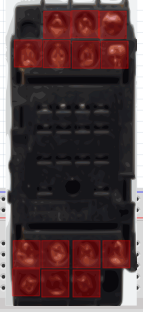
What I want is
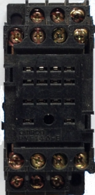
I have hidden the pads in inkscape but they still show in fritzing, is it possible to hide them?
omron for the forum.fzz (363.4 KB)
The second problem is I am trying to use fonts whilst making the schematic of the relay base and fritzing only supports OCRA and droid fonts, it substitutes anything I use including OCRA Extended, which is the only one inkscape uses and changes the size of the font dramatically. Is there any way around this?
Bob
If you only have a few problems you are doing very well already (as is indicated by your breadboard example here).
[quote=“matelot, post:1, topic:7443”]
The first one is in the breadboard view.
The picture I get after assigning the pads with inkscape is
image
What I want is
image
I have hidden the pads in inkscape but they still show in fritzing, is it possible to hide them?[/quote]
Unfortunately no, the best you can do is make the red dot smaller. What is happening is Fritzing is coloring the connector pin red to indicate no selection, when you connect a wire it will turn green. In this part (which has a new moduleId so you can load it along side your current one) I did the following in Inkscape:
ungroup the entire drawing move connectors in sequence to the bottom via xml editor set style to fill:none;stroke:none;stroke-width:0 for all connectors reduce height and width from .222in to .01in for all connectors and move them back to the center of the pin. Align all pins so y is the same across the line and X is the same as all the pins above it so the pins are in a square matrix so the wires connect neatly (preferably on .1in boundaries but these look to be .056in or the like terminals). edit->select all, Resize the page, group and name the group breadboard (to set the layerId so the part will export as svg) then save as plain svg.
omron relay-modified.fzpz (337.9 KB)
which produces this:
which still has the red dot (as there is no conection) but it is now much less obvious.
Have you loaded the Fritzing fonts from the main website?
http://fritzing.org/learning/tutorials/creating-custom-parts/download-fonts-and-templates/
If you install the fonts in the download Inkscape will find and use them. If you want to use alternate fonts for some reason (although I dislike it, as it makes changing parts much harder!), you can change the font in to a path as well. In addition I ran your part through the part checking script and there are a number of other errors in it, but I just addressed this particular problem here.
edit:
If you are making parts, it is a good bet to download and use the 0.9.4 pre release version from github. I fixed a couple of bugs where badly formatted parts will hang Fritzing that are in that build. Instructions on finding it are here:
Peter
thank you very much for your efforts
Hi Peter,
The ID is the same as from your other part. Can it be changed to “Microbit-breakout_2”? (I can’t seem to unzip it with iZip)
Kris
Easy enough to do. I have replaced the first one with a _2 model with the changes. It is perhaps more complex than you expect, you need to change the _1 in all the file names to _2, then edit the fzp file and change the moduleId and reference file from _1 to _2, change the variant to 2 and change all the image file names to _2. The new part needs different fzp and svg file names, a different moduleId and variant number to co exist with the original one. If you load both at the same time Inspector should let you select which variant you want and swap one for the other (as they are identical except for color)
I use 7zip on Windows, I’d guess the .fzpz may be confusing iZip. 7zip doesn’t care what the extension is, it appears to look at the file contents to see if it is a zip file or not.
Peter
OK, thanks!  Next time I use my Windows7 Virtual Machine.
Lady luck is with me , it appears that eagle2fritzing only needs the development environment the first time it runs. It copied all the dlls it needed in to its working directory which was on another disk, so I ran eagle2frtizing last night and am now most of the way through your part, should be up today sometime if we are lucky.
Peter
hello everyone,
I’m looking for rocker dpdt switch (6 pins) in fritzing but had no luck finding it. can someone help me with the part or create a new one for me if it isnt available? i’m attaching pictures for reference.

Thanks in advance.
Regards
Karthik
I didn’t rename “my parts”… That’s why It’s not creating new bin… Also can’t load 2nd batch file with 1st one…
Found the bin registry file here…
That’s why new downloaded fritzing also having the duplicate bins… I had to delete duplicate bin from here…
I renamed in the .fzb file, now it’s working good…


To make a part we would need the data sheet with the dimensions of the switch. This doesn’t look like it will fit on a pcb, are you intending on using wires to connect to the pcb? The rectangular pins are a problem as Fritzing doesn’t do well with slots in pcb. Wires make life easier …
Peter
Thanks for the quick response, Pete. Since im new here, Fritzing isnt allowing me to attach more than one pic. I do have the dimensions for the switch. I’ll add it once i’m allowed to do so. I don’t intend to use wires and was planning to solder it onto the pcb. now i’m confused whether to solder or use wires 
Regards
Karthik


