My fault, I was looking at the svg after I had run it through the script. The one posted is indeed white in silk when I re unpacked it.
Sounds like the upload without that is already done …
I don’t agree  and the parts format document is ambiguous:
“The terminalId attribute is optional. Each connector takes up a certain area in a part (in the example above, it’s a rectangle), but a wire will actually attach to a connector at a single point within the connector’s area. This point of attachment is called a terminal point. The default terminal point is the center of the connector area. If you want the terminal point elsewhere, the terminalId attribute points to yet another element in the SVG file. Here is the SVG element for the terminalId attribute “connector0terminal” in breadboard view:”
TerminalId is indeed optional, as it says, if you omit it, then the wire connects to the center of the pin. In breadboard that is often fine as the pin is square and the center is where the connection should be. In schematic I think it is less fine as the pin is usually .1in long by 10 thou wide which means the wire will connect .05 in from the end of the pin which to me looks ugly. The n/s/e/w setting for terminal in parts editor will set this correctly and sets the terminalId so I think it can be argued either way. Most (but certainly not all, although I think that is an oversight rather than intention) of the parts in core have terminalId in schematic at the appropriate end of the pin. My script warns (but doesn’t error because it is optional) if that is not the case. I’d like to see us come to a consensus of what we would like to see (and I’d like to see terminal on the end of the pin as is possible now) and lobby and/or help make that true of the new design if it proceeds.
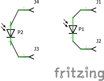
In fact in this case there seems to be an error in your uploaded part. For this the diode on the right (p1) is the one from core and the one on the left (p2) is your new part. The original is what I would say is correct in schematic. Yours lacks the terminalIds (which the original obviously has although I didn’t check the svg). As well your pins appear to be offset from the .1in grid by .05in. That should mean the part submitted to github should have schematic correct, but not the scale nor silkscreen being black but neither of those are vital.
Peter