This should help…
First, recognize that dimensionally, decimal places of 0.1, 0.2… up to about 0.5 mean very little when placing components on a pcb as the pins are flexible enough and the holes are large enough.
Second, the outer dimensions of 11.0 to 12.5 are fairly irrelevant unless you’re trying to squeeze a square peg into a round hole, so to speak.
Meaning, ‘ballpark’ dimensions have been good enough for me and stuff I have flying in outer space for the past 40 yrs…
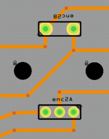
Having said that, attached is what I use for all of my 12mm (approx dim) encoders (ALPS, BOURNS, PANASONIC… many others). Some of the actual encoders are 11mm, some 13mm… But, the pin spacing is what is important and the ones I use are all within about 0.5mm of each other.
Attached is a file of what I use as a baseline and will work for you. Sure, you can move the pins&holes if you must but, there’s no need… The screenshot is from actual part in a circuit on my desk…
enc_Baseline.fzz (1.5 KB)