Sorry for the late reply, I have been offline for a couple of months with a broken ankle. The part check script is a python script (available on github) that checks the xml of a part against the parts file format document and reports errors. It isn’t all that easy to use if you aren’t familiar with what a correct part should look like. In the case of your part it (and I) find a number of errors. The svgs are missing layerIds. If the layerid in the svg doesn’t match the fzp file then pdf and svg export on Fritzing don’t work. Breadboard has termanalId specified in the fzp file but not the svg (this doesn’t really affect anything in breadboard), and the same in schematic where it does matter. As well it is desirable to have the outline of the board (so the area it takes up on the pcb is visable during layout) as a silkscreen layer in the pcb svg. This image shows the problems in the schematic svg:
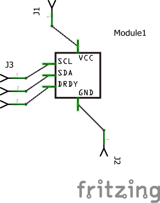
The connection to the middle of the pin (rather than the end which is desirable) is caused by the missing terminalId. I use a 10 thou by 10 thou rectangle labeled connectorxterminal
(where x is 0 to 4 depending on the pin number in this case) aligned to the end of the pin. As well your part isn’t aligned on .1 in boundaries so it doesn’t match with other parts.
Peter