Hi all,
New to Fritzing but hooked. Already done one project with a dimmer.
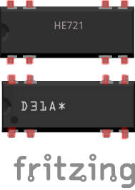
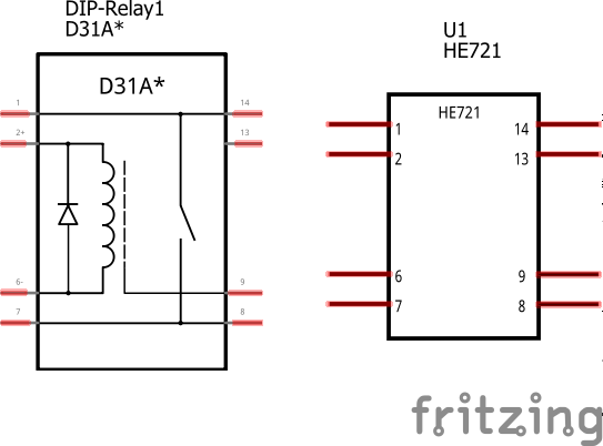
Now looking at building a thermostat using amongst other a DIP reed relay, HE721. Cant seem to find that part anywhere, nor anything with same pins.
http://m.littelfuse.com/~/media/electronics/datasheets/reed_relays/littelfuse_reed_relays_he700_datasheet.pdf.pdf
Any tips on where to find one, or get one created 
Thanks,
Richard