Quantcast
Channel: fritzing forum - Latest posts
Viewing all 31230 articles
Browse latest View live

A discussion of future direction

$
0
0

I feel that the parts editor needs to be finished so we can stop working with XML files and doing everything manually and instead do it all in the editor. It seems that a lot of what you want is the result of your trying to make things as strict as they had to be before the editor was built. It also appears that the editors purpose it to make parts creation easier by allowing things to be assigned however they are and not have to have everything perfect as you would like. I personally like that you can do things how you want and that you do not have to follow strict guidelines to get a working part.

I personally do not like forced standards as they stifle innovation. If no one had gone against convention we would still be using a rock as our most advanced tool. Allowing people to work the way they are comfortable lets them be the most innovative.

When I make parts I make an SVG of the part with the copper in copper groups and and a silkscreen group, that is all. All other assignment is done in the editor. It takes no time and you never get it wrong. Sure things might look ugly in the XML but if you never look at it who cares what it looks like. 300 groups deep, who cares it still works and I never have to deal with it. It only takes a couple of minutes to make an SVG if you don’t have to worry about making terminals or assigning names to each pad/ring etc. Then it takes only a few seconds to assign the rest with the editor. To make a part completely via SVG and XML it takes much longer and if you have started from an existing part you are likely to have errors. If you start the SVG from scratch it never has strange extra transforms etc. I haven’t had errors making parts since I stopped trying to edit existing parts and started drawing new SVGs. I also keep the original SVGs I create for editing later so I never have to open the Fritzing modified SVGs.

Do note that none of what I have said is in regards to the breadboard as I do not use it and wish it could be turned off when not used to speed up loading and to reduce the risk of errors as it only seems to be possible to corrupt a sketch when using the breadboard and making changes in the other views. If you never work in the breadboard you can make changes between views repeatedly without causing the mysterious extra ratsnests bug.

I know that all of my parts create perfect PCBs and readable schematics. I also know that my parts would fail most if not all of your scripts tests. Does that mean my parts are no good? No. They are all perfect (for me) and work exactly as designed. If you run the part I uploaded MCP1700-xx, SOT-89 through your script you will likely see what I mean. With that all said I think people would rather have as many parts available to them as possible even if they are a little buggy if the other option is nothing making it into core parts because of strict standards. Obviously incorrect foot prints and similar issues that prevent them from being used need to be fixed.

All of the above is my personal opinion and is not intended to make your opinion any less valuable.


A discussion of future direction

$
0
0

This is engineering so I think there should be rules.
I hate adding parts to SCH and finding a simple 8 pin box part bigger than a MEGA2560.
I hate going down 300 groups to fix one little thing.
I hate silks that aren’t black making it hard to do a icon hover to see what it might look like.

Now that I know how to draw in INK you are right about not trying to fix parts but starting from scratch. This is ok for SCH and PCB, but BB is a bit hard.

EDIT

I actually have no problem editing in any view at any time. All I do is picture the part in the other view and what will happen - I will switch view if i don’t remember -, and note the pin #'s and not force what I think is right but use the rats. Sometimes it will leave a rats, but you just check it in other views before you delete it.

A discussion of future direction

$
0
0

This is already being successful, because people are discussing what they would like, which is what I was hoping for. Hopefully more folks will provide input.

The script does fix this one. Anything on the silk layer gets translated to black.

Agreed, if it worked better I might actually use it, so that should be added to the list of things to work on.

Mostly the script is aiming to make parts maintaining easier. If the parts maintainer can run a proposed part against a script it should give a good indication if the part is suitable. Many people appear to be cloning parts (often from core, and getting bad places to start) at least some of them are probably using the parts editor and some are like me ignoring it and editing the xml directly, Having standards that the script will report on doesn’t necessarily mean that parts that don’t conform (at least at the warning level, where there isn’t a known problem that it will cause in fritzing as opposed to Error which does cause a problem of some kind in Fritzing). The choice is with the parts maintainer, but the task is automated more than it is now.

Not really, because while the output is verbose, there is nothing more serious than a warning, and that is only because silk is below the coppers which apparently makes selection difficult. There would be no reason to reject this part (as long as it was run through the script first, as it did remove a bunch of font-size pxs which do break Fritzing and convert the silk from grey to black as it should be). The reference file stuff can be ignored, nothing actually looks at the reference file field except possibly humans as far as I can see.

$ FritzingCheckPart.py part.MCP1700-_819072743e0b360180d372f1c811f2ae_1.fzp
File
’part.MCP1700-_819072743e0b360180d372f1c811f2ae_1.fzp.bak’

This is a smd part as only the copper1 view is present.
If you wanted a through hole part add the copper0 definition before line 40

Modified 4: File
’svg.breadboard.MCP1700-_7352f054c1e7d8f2e2ab28ceee875bbd_1_breadboard.svg.bak’
At line 14

ReferenceFile

‘sparkfun-poweric_sot23-3_breadboard.svg’

doesn’t match input file

‘MCP1700-_7352f054c1e7d8f2e2ab28ceee875bbd_1_breadboard.svg’

Corrected

Modified 1: File
’svg.breadboard.MCP1700-_7352f054c1e7d8f2e2ab28ceee875bbd_1_breadboard.svg.bak’
At line 47

Removed px from font-size leaving 65

Modified 4: File
’svg.schematic.MCP1700-_7352f054c1e7d8f2e2ab28ceee875bbd_1_schematic.svg.bak’
At line 14

ReferenceFile

‘sparkfun-poweric_lm3480im4_schematic.svg’

doesn’t match input file

‘MCP1700-_7352f054c1e7d8f2e2ab28ceee875bbd_1_schematic.svg’

Corrected

Modified 4: File
’svg.pcb.MCP1700-_7352f054c1e7d8f2e2ab28ceee875bbd_1_pcb.svg.bak’
At line 5

ReferenceFile

‘sparkfun-poweric_sot23-3_pcb.svg’

doesn’t match input file

‘MCP1700-_7352f054c1e7d8f2e2ab28ceee875bbd_1_pcb.svg’

Corrected

Modified 3: File
’svg.pcb.MCP1700-_7352f054c1e7d8f2e2ab28ceee875bbd_1_pcb.svg.bak’
At line 14

Silkscreen stroke color #f0f0f0 isn’t white or black. Set to black.

Modified 3: File
’svg.pcb.MCP1700-_7352f054c1e7d8f2e2ab28ceee875bbd_1_pcb.svg.bak’
At line 15

Silkscreen stroke color #f0f0f0 isn’t white or black. Set to black.

Modified 3: File
’svg.pcb.MCP1700-_7352f054c1e7d8f2e2ab28ceee875bbd_1_pcb.svg.bak’
At line 16

Silkscreen stroke color #f0f0f0 isn’t white or black. Set to black.

Modified 3: File
’svg.pcb.MCP1700-_7352f054c1e7d8f2e2ab28ceee875bbd_1_pcb.svg.bak’
At line 17

Silkscreen stroke color #f0f0f0 isn’t white or black. Set to black.

Warning 6: File
’part.MCP1700-_819072743e0b360180d372f1c811f2ae_1.fzp.bak’
At line 2

ReferenceFile name

‘sparkfun-poweric-lm3480im4-.fzp’

Doesn’t match fzp filename

‘MCP1700-_819072743e0b360180d372f1c811f2ae_1.fzp’

Warning 25: File
’svg.pcb.MCP1700-_7352f054c1e7d8f2e2ab28ceee875bbd_1_pcb.svg.bak’
At line 13

Silkscreen layer should be above the copper layers for easier selection
in pcb view

This last message (which is why it is last) is the only one that might be worth doing something with. The pxs and style commands have been inlined (and it told you what it changed just in case you care, which you usually don’t) but it is a Warning because it doesn’t break anything, The px does breaks something, but it got corrected. Running the script again (against the corrected output from the first run) gets even less, as it has fixed what it complained about mostly (I need to change the fzp ref file which it currently doesn’t):

$ FritzingCheckPart.py part.MCP1700-_819072743e0b360180d372f1c811f2ae_1.fzp
File
’part.MCP1700-_819072743e0b360180d372f1c811f2ae_1.fzp.bak’

This is a smd part as only the copper1 view is present.
If you wanted a through hole part add the copper0 definition before line 40

Warning 6: File
’part.MCP1700-_819072743e0b360180d372f1c811f2ae_1.fzp.bak’
At line 2

ReferenceFile name

‘sparkfun-poweric-lm3480im4-.fzp’

Doesn’t match fzp filename

‘MCP1700-_819072743e0b360180d372f1c811f2ae_1.fzp’

Warning 25: File
’svg.pcb.MCP1700-_7352f054c1e7d8f2e2ab28ceee875bbd_1_pcb.svg.bak’
At line 64

Silkscreen layer should be above the copper layers for easier selection
in pcb view

So your part is in better shape than you thought (and in even better shape now :slight_smile: at least in this version)

Peter

En555 timer create a alternating flashing light

$
0
0

Found a flashing light schematic on facebook. Crossing Circuit Ben Hanna 
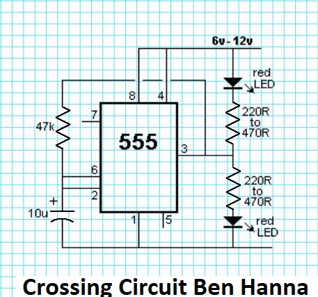
Not able to gt it too work. Found Fritzing and attempting to create Schematic in this program. Can get the LED’s to light up using the 555 timer, not blinking. What do I need or am I missing in this project?

.
TIA

High power rgb led moving robot lights controlled via esp32 , need help vetting circuit designs

$
0
0

didnt know you could just input a value like that , thanks!

Complicated PCB picture to showcase Fritzing

$
0
0

I’ve had some bad news that the project I’m interested in is switching to KiCad, stating that they have out grown FZ, and I remembered a much more complicated FZ PCB posted that I wanted to link to show FZ doing very complicated stuff. The problem is that I have just spent many hours trying to find it but no luck, so I started this post if anyone want to post impressive FZ PCBs we can link.

En555 timer create a alternating flashing light

$
0
0

There is so much wrong here I just started from scratch.
First the power supply part looks to have a problem as it causes routing errors. So I started with a blank sketch and used the parts search to search for 555, picked the dip 8 version (which is probably what you actually have) and dragged it in to schematic view. Then I searched for battery and dragged the 9V battery in to schematic. Then a capacitor and used inspector (lower right window) to change the value to 10uf. Then a resistor and again used inspector to change the value to 47k. Then two more resistors left at the default 220 ohms. Then two leds. Which completes the parts. Now in schematic and breadboard views drag the parts til they match this sketch:

initial.fzz (3.8 KB)

Now in schematic connect the capacitor and the 47k resistor, and the two 220 ohm resistors and the leds as shown in this sketch:

bb_align.fzz (4.3 KB)

now switch to breadboard view and look at the lines that
connect the resistors and the leds and the 47k resistor and the capacitor. If yours don’t match the sketch then select that resistor and right click and select rotate 180 degrees til they do match. It is important that the alignment in schematic match that in breadboard. Now connect the rest of the wires in schematic giving sketch

schematic_done.fzz (6.8 KB)

now switch to breadboard and connect and route the light colored lines to match the final sketch;’

complete.fzz (9.9 KB)

and if you wire your real breadboard to match this then the circuit should work.

Peter

Complicated PCB picture to showcase Fritzing


RP2A03 NES Chip Part

$
0
0

Does anyone know if a part exists for the RP2A03 out of an NES?

Start up error message - openssl

$
0
0

Steps I took that resulted in the problem:

  1. Start Fritzing
    Get error message:
    Window title: Fritzing.exe - Entry Point Not Found
    Message: The procedure entry point EC_curve_nist2nid could not be located in the dynamik link library C:\Program Files\OpenVPN\bin\ssleay32.dll

What I expected should have happened instead:

Fritzing starting without error message

My version of Fritzing and my operating system:

0.9.3 Windows 10 64 bit latest release (autoupdate)

Please also attach any files that help explaining this problem
##ScreenShot205

BTW, what does Fritzing use OpenSSL for to start?

Perfboard resizing how to do

$
0
0

Are there some minimum sizes? E.g. if I choose 2 x 2 and press resize, it does not resize nor does it give any error message.

RP2A03 NES Chip Part

Need foot print for ATSAMD21G18

$
0
0

I found only ATMEGA foot print on my fritzing program. Where can I get AMD21 foot print? I guess it is QFP48. Is it work with SMD_LQFP-48.fzp?

Thank you,
Somsak

Perfboard resizing how to do

$
0
0

Must be because mine is the same. 2 rows x 2 rows seams not very useful, so maybe it’s like that. 5 x 5 is the smallest I can go.

Complicated PCB picture to showcase Fritzing

$
0
0

Nice, but it looks like it’s too late because the guy likes KiCad. They guy said it’s faster, but that is probably due to more parts because I found it slower having to do the same thing multiple of times. Basically you pick parts, lay them out, export the parts, pick footprints for parts you already picked, import parts in another view, and then lay them out. Oh well looks like I’ll have to switch to KC.


Need foot print for ATSAMD21G18

$
0
0

I think the L is low profile QFP-48, so I would assume they are the same. Best to compare both datasheets for dimensions of packages, and then check the FZ one.

Need foot print for ATSAMD21G18

$
0
0

In PCB view, how can I measure the length.

Need foot print for ATSAMD21G18

$
0
0

I usually put the part in PCB and zoom right in until it’s huge, and move the cursor from one side to another and read and subtract the x.y cord in the bottom right - click on it to change units -

If you want more accurate you right-click on the part and select Edit, goto PCB, then File/Show in Folder and save that svg. Then open it in Inkscape and use the ruler.

You can also print the part and see if the part fits on it, but it’s hard to see small legs.

Need foot print for ATSAMD21G18

Start up error message - openssl

$
0
0

Fritzing does not use openssl directly but it does check for parts updates when started and since you are using a VPN all of your traffic is being redirected through your VPN which does use openssl to secure its connection. So your problem is not with Fritzing but rather with your installation of openVPN.

Viewing all 31230 articles
Browse latest View live


<script src="https://jsc.adskeeper.com/r/s/rssing.com.1596347.js" async> </script>