Went to the sight and the screen does not show anything on computer. Will try with a different browser.
Need help for an Arduino connection
Need help for an Arduino connection
Nope, nothing in Chrome either.
Need help for an Arduino connection
Firefox pulls up a test.fzz file for me on Windows.
Peter
Need help for an Arduino connection
Looks like you have the rfid unit connected fine (I’d probably rotate the rfid device 90 degrees in schematic to make it more readable and align the wires to the grid, but it should work as is). That said there isn’t any indication of what you are trying to do so it is hard to provide any help. I’d assume that you want to connect the motor to the motor driver board and the motor driver board to the arduino and the touch sensors presumable want to go to analog ports on the arduino (simply because there description says resistive). There should be articles on the net on how to do those things.
Peter
Need help for an Arduino connection
In the lower right hand corner of the page under DOWNLOADS is test.fzz.
A discussion of future direction
I have read that, I just wasn’t involved in Fritzing at that time so am not all that knowledgable on the history involved. I can clearly see the results though  , the underlying design of Fritzing is awesome and very well thought out.
I’m hoping my parts checking script (unfortunatly along with a lot of work) will help correct that. I’m working on cleaning up the Raspberry PI family (the zero is already done as it was broken) and will branch out from there, with priority to broken parts (with pauses to fix the script as it breaks  ). That’s why I started this thread as what I want may not be what the community wants or needs.
Even worse is that the two of them have different (and not very compatible goals: Fritzing want’s the svg tiny subset and Inkscape wants to be CSS compliant which Fritizing doesn’t fully support. Neither is wrong, their goals are just different. Again my python script is partly designed to fix that. It takes the output from Inkscape and modifies the parts of CSS that Fritzing doesn’t support in to equivalent xml (I hope) for Fritzing (current inlining style commands and removing the px from font-size commands). Ideally the script would move in to the Fritzing load routines to occur automatically on load, but that is a future. I’d like to see the script remain external to Fritzing (just called from load) so the script can change to track Inkscape changes without having to do a new release of Fritzing but we will see.
Hopefully that will become true, although I suspect breadboard is mostly still going to need an svg editor for many types of parts, but for it to happen we need to get people developing. There is light at the end of that tunnel though, the development environment is now working again and I (and I hope others) are working on fixing some of the bugs. I have a fix for the segfault and hang caused by a corrupted part submitted as a pull request and am working of figuring out how to get parts editor to delete the files it creates in the mine parts bin when it makes a part (this is considerably more exciting to do than the first fix). If we can come up to speed on the code base we may be able to start working on parts editor. There is a todo list in the source that describes some of what they thought should be done next.
Peter
A discussion of future direction
I think the guy wasn’t interested in finding out what happened - or he would’ve supplied the .fzz -, he just wanted someone to blame. The drill.txt showed 3.1, 3.8, alternating holes, so if the PCB came back with 3.8, continious it wasn’t FZ’s fault.
The part checking script is good, but it still leaves the problem of miss labeled parts, i.e. a 3.5mm screw terminal that is actually a 3.81mm.
Error when importing an SVG for a custom part with top and bottom layer
Any idea on how to do this with illustrator?
Error when importing an SVG for a custom part with top and bottom layer
Unfortunatly, no I’ve never used Illustrator. I expect it would be in a similar place since it affects the formatting for the entire document. Hopefully someone familiar with Illustrator can chime in with how to do it.
Peter
Error when importing an SVG for a custom part with top and bottom layer
Hmm okay - I tried to open my illustrator file in Inkscape and follow your description but it does not come out right unfortunately.
Error when importing an SVG for a custom part with top and bottom layer
What goes wrong? It may be easiest to upload the svg (you may need to rename it to fzpz as sometimes the forum doesn’t like rendering svgs) and I’ll keep a log of what I have to do to rescale it.
Peter
A discussion of future direction
BB view is very useful, and my suggestion incorporates that. I may not use it as much as you, but it’s still there! I am a results-oriented person, and I tend to favor the simplest and easiest path to arriving at desired results. To this end; by suggestion was to simplify the parts process into a simple modular “group” of elements to serve the same purposes as the current parts and editing, without locking into a zillion parts that only serve one function. Here is a quick example of what I mean:
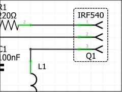
Let’s say we want to incorporate an IRF540, and there is no part. Easy. In schem-view, drag out some pins, and “group” (function) the pins and attributes (Goup Name: IRF540, Part Class: Q, Pin Numbers: 1,2,3, Image: TO-220, etc.) It looks like this in schematic view:

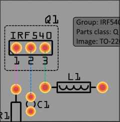
And connects like this in PCB view:

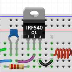
And appears like this in bread-board view:

A handful of generic images including standard transistor types, adapter boards (non-specific like they are now, which all look the same but are repeated for each different part), resistors, and so on. Instant parts, without megs on megs of individual and difficult-to-edit parts, and always without the exact one you need. I’m sure there is a more logical or sexier way to represent them, but it’s a quick example of concept. Is this too simple? What am I overlooking? Thanks for your input.
PCB errors don't match Fritzing?
OK, so I did some tight measuring in GerbV as suggested to me, and indeed the gerber’s row of blocks is 70mm on the nose. So, I measured the PCB with calipers and it is also about 2.6mm oversize. It would seem the whole thing “grew” a couple percent, but not in the Firtzing output. it seems (other than the incorrect 3rd party part pin spacing) that Fritzing did its job. Thanks for all your help and suggestions!
PS: Old_Grey, the board is oversized a bit, so the block tabs are not the issue, and in-fact they are not working like they should. So, it looks more like a social party than a row of soldiers. 
A discussion of future direction
I know what you mean, and you can do something similar by locating vias off the PCB and group moving them in, it’s just that all EDAs use a complete footprint for a part so that method seams like a patch for the more common way.
When I started I had trouble with the complexity of svg drawing - it’s nothing like raster GIMP - so I used every method to skirt around actually learning how to draw in INK - I imported pdf drawings -, but once I learnt to draw parts, which isn’t that hard, I find it a snap to just do the correct footprint and import it into a new part.
I made a tutorial video series that teaches you both FZ part making and INK drawing all in one hit, and that 90min will save you 10’s of hours fumbling around.
KiCad has more features, but the clunky way you have to use it is like going back to the stone age - it’s a lot of separate programs under one wrapper that don’t talk to each other -. You select parts for the SCH, layout the circuit, export the parts from SCH, import into PCB, pick footprints for the parts - SCH and PCB drawing are not joined -, and lay them out again. And I think if you change something in PCB you have to also do it in SCH, because the views aren’t connected. I suppose you get used to it - you have to learn a lot of short-cuts -, and it has some cool stuff, but simple things like a junction you have to grab like a part, where’s FZ you right-click or pull a trace. When I started 2 years ago I trialled FZ, Eagle, and KC after watch hours of tutorials - it’s the only way to learn them quick - and I liked FZ, maybe you’ll like something else.
A discussion of future direction
I think what you are suggesting is already present in the mystery part. Where it falls down is when you need a custom footprint. I expect as @steelgoose said earlier the correct answer is to finish the parts editor (which is currently not finished). To do that we need to get people willing to put time in to development which currently isn’t happening (or at least not happening enough).
Peter
PCB errors don't match Fritzing?
There is something wrong with that because nothing would ever fit if every time you sent it for production and it was scaled up. A 40pin straight-line header would have trouble fitting with a 1% scale, yet alone a 3%. I would be checking the dimension of 2 far apart holes perpendicular to the screw terminal row on the PCB and comparing it to what it’s supposed to be in FZ - the size of the PCB compared to FZ size might be enough -.
Can not connect to pins on already existing part
Hello,
I downloaded the Esp-wroom-32 part for Fritzing (the chip). The chip already has all the connections as in the product specifications only that from the 38 pins 12 pins are like disabled… Whatever I do I can not connect to them. I entered the parts editor but still I can not figure out what is the difference between the other pins (IO) and these 12.
For now I will connect the rest of them and do some modifications from the electrical diagram with the connections that I have but the question remains … How can I activate the existing 12 pins that now are disabled?
Thank you for your time. The link with the Fritzing part that I discuss about is:
Befuddled by the terminology and lost in the technology!
Hi Peter,
Sorry I haven’t replied earlier, but was called away on a personal matter.
Wow you have been busy, this is very kind of you, thanks very much.
I’ll have a look at your notes to see how I can improve my skill set, but thanks again for taking the time to do one and explain how you achieved it.
I’ll now go and have a look at it.
Cheers,
Rich
Befuddled by the terminology and lost in the technology!
Hi Barnys1,
Sorry for the delayed reply, I was called away on a personal matter.
Thanks for your suggestion.
Cheers,
Rich
Can not connect to pins on already existing part
It is not that hard to assign pins in the editor. Right click on the part and open in the parts editor. Go the connections tab and set the total number of pins. Then go to each view and click on the unassinged pins in the connector list and click select graphic and then select the pin on the graphic. Do that for all the pins that do not have check marks already. Once you are done you should go into the meta tab and make any changes you feel are needed as well as assign the pin names in the connections tab and then save the new part ( I have not tested it an do not know if it has any issues ).
Also are you aware that is not just an esp32 module but rather a breakout board from a specific company for a esp32 module. There is an esp32 module available by itself.


