Got it. Thanks!
I have found this answer somewhere else. However I did not know where the inspector is. I googled it and now I can change the colors of all items.
↧
Changing the color of LED
↧
Arduino Mega 2560 Shield v2.0
There are a lot of messages on this thread and I’ve not had the time to read all of them; just to say:
I created the latest version of the SVG and had intended to turn it into a working part, but ran out of time. If you have any questions about it I would be happy to help. I put a lot of work.into getting the layout right.
However, be aware that the pin alignment on the svg of the DF board does not match Fritzings Mega 2560 for two reasons: 1 the two actual physical parts are slightly different dimensions - they fit but there is strain 2.The dimensions for the 2560 part in Fritzing are wrong. I checked against the orginal.CAD files and I have a (modtly) complete revised 2560 part but never got that completely finished either.
Also note: DF change theIr boards a lot. Your work could very easily be wasted.
↧
↧
12V Lead Battery
Hello Fellow Fritzers (if you don’t mind us being called that),
I am on the hunt for a 12V Lead battery to add into my Fritzing diagram. Does anyone know of an existing part that fits this category? Please see this link for the exact part I have, but obviously it doesn’t have to be that specific. I’d rather have one part than multiple battery packs connected in my diagram. Any help would be appreciated!
↧
Request - IRF520 MosFET module
Looks good, only 2 minor nits, there isn’t a layerId in the schematic svg, you need to do a select all, group and change the id to schematic to fix that. The only thing that breaks (as far as I know) is the part won’t export as an svg, this part will be missing.
The other thing is the pins on the screw terminals in breadboard are slightly off the .1 grid. It is preferable that they are on the grid, doesn’t affect function just looks a little messy. You have caught on to parts making quickly!
Peter
↧
Request - IRF520 MosFET module
I noticed the screw terminals, but in order to make them fit the 0.1 grid, I should either rescale it (the screw group) which would make it smaller (and ugly) or move them away from each other. Not sure what I should choose.
About the schematic, I forgot it! 
↧
↧
Request - IRF520 MosFET module
I’d probably move the screw terminals on to .1 boundaries, if the wires connect a bit off center in the connector, to me that’s better (as in visually less jarring) than the wires being at an angle, but that may only be me. Which to do (or leave it as is) is a personal preference. If the schematic layer id is the only thing you forget you are doing pretty good  . It took me many many months to make parts like this and you look to have picked it up in a couple of weeks.
Peter
↧
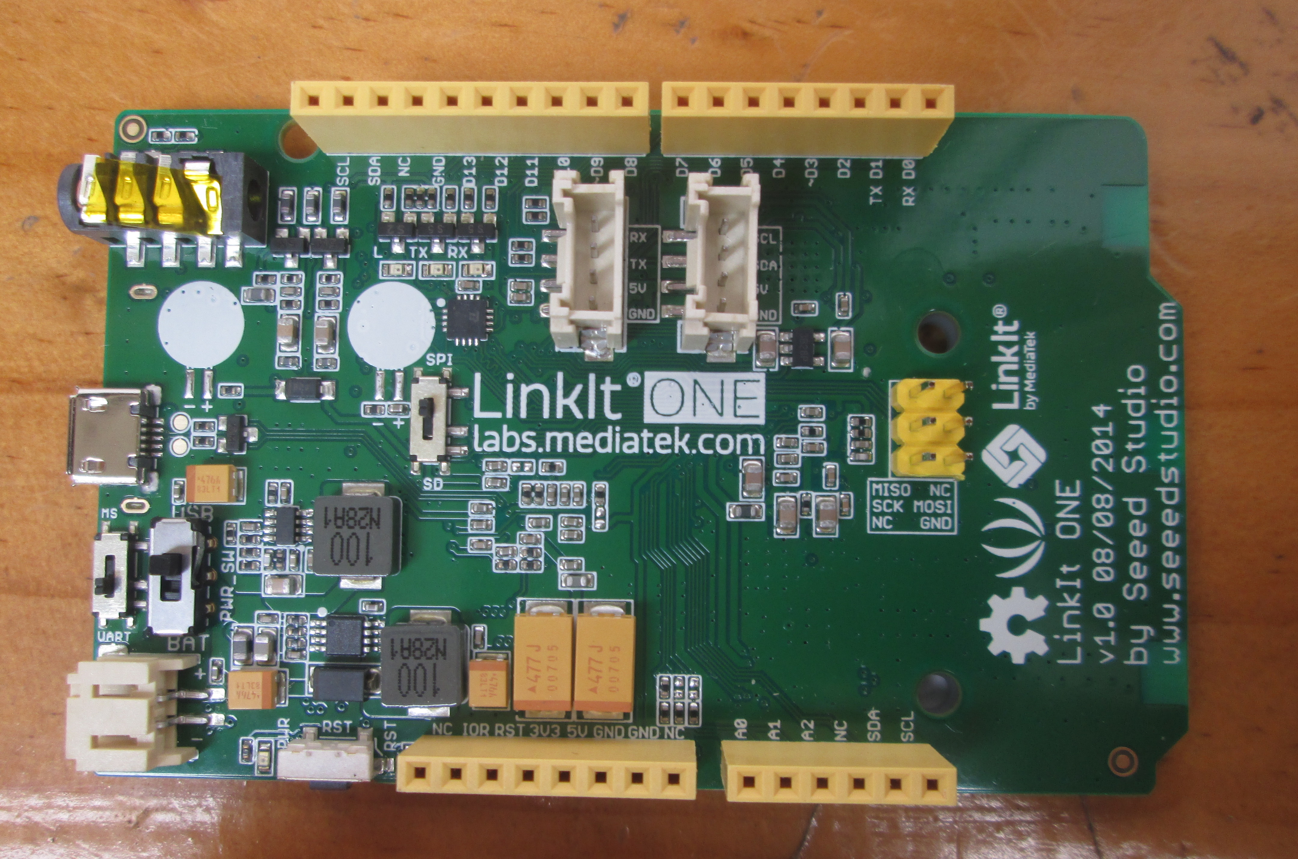
LinkIt One Development Board
I went lazy for the schematic and pcb view for now but atleast I finished (I think) the breadboard view. I know it hasn’t been rescaled but I just want to read your opinions.
LinkIt_One_mod2.fzz (32.2 KB)
I zipped it with 7zip, but you should be able to change into .svg and open it 
Changes done from Old_grey based on this link:
- Replaced the headphone jack for a better one.
- Added the three slider switches.
- Replaced the battery connector.
- Added reset key (the one at left of yellow headers).
- Added logos.
- Added box description for ICSP.
- Removed lower left hole.
- Moved the two big white headers.
- Aesthetic details (resistor, led, etc)
↧
LinkIt One Development Board
7zip, so that’s why I can’t open it.
If you made the part just export it from FZ in .fzpz format.
↧
LinkIt One Development Board
Looks fabulous! You are much better at the graphic art side of this than I am, hopefully we can convince you to keep making parts . I only see two issues at a quick look both connector related: it is desirable (but not the case in many parts) that connectors start at 0 and go up in sequence to the number of pins-1 which isn’t so far the case here. The reason is that Fritzing is expecting (and assumes) the next pin will be sequential when it creates the labels from the fzp file. If you have connector6 (pin 7) label x, no connector 7 and connector 9 (pin 10) label y if you hover on the pin in breadboard pin 7 will show label x, pin 10 show pin8 (which doesn’t exist) and I think a random label (it may be pin 11 which will show the random label) and then it will recover and label the pins properly. A minor issue but annoying and not correct. The other issue is that at least connector16 and 17 on the battery plug aren’t on the .1 grid, but over all a beautiful job.
Peter
↧
↧
LinkIt One Development Board
The pin labels should be the std UNO config.
↧
LinkIt One Development Board
Any zip program should open 7zip files perhaps unless he used the .7z format. By default in my case 7zip uses .zip format but I have seen .7z files which 7zip happily reads but other packages may not.
Peter
↧
LinkIt One Development Board
I’m not sure that is correct. This board is a CPU and has its own pin names that may or may not match the UNO. I’d be inclined to use the labels on the LinkIt pinout page (which of the several for each pin is an issue though ) so it matches the documentation for the board because that is likely what the user will refer to.
Peter
↧
Searching for ST7735B - 128x160 TFT LCD Display part
I’m mostly finished a modification of the adafruit part to convert it to this. I’m done for tonite and busy tomorrow but a part should be along soon (only pcb and the fzp file to finish). I found board dimensions (if not hole nor header placement which are just guesses) on ebay so it won’t be quite correct unless you can measure the placement of the holes and the pins with calipers but it should do the job. The adafruit part looks to be the alternate layout for this same display (only 10 pins instead of 16, different mounting holes and board size).
Peter
↧
↧
LinkIt One Development Board
Sorry, what I meant was that if you add a the std UNO BB svg into a new part with Part Editor and it AUTO assigns then that part should auto assign because it is an extended UNO. All you just have to relabel the names in Connector. If it doesn’t auto assign then then it doesn’t matter.
Basically I was thinking if UNO svgs auto assigns and you modify the 3 UNO svg and it would already be assigned when added to a new part. But if that’s not the case it’s not many pins to assign.
Damn I don’t have 7zip and it won’t unpack. Should have Send to Compressed folder in Win.
↧
LinkIt One Development Board
That’s nice, just some of the header labels look like they are still the old UNO.
I’ll start on the PCB svg and hope it’s the same as UNO with the right-hand side extended 0.600"
↧
LinkIt One Development Board
That sucked, the std UNO PCB view wasn’t to scale.
Rescaled Uno PCB, extended 0.600", and changed the pin silk names.
Change to svg
LinkIt_One_pcb.fzz (78.2 KB)
I hope I got/removed all the px.
↧
Hi Ya'll, noob here :)
Hi y"all as I am totally new in the world of Arduino and set my goal way too high I stumbled onto Fritzing and must say I am stunned, what a wonderfull way of documenting, designing and getting to know it all.
Now to my quistion, is there a way that you can add a HTML or HTM file to your fritzing project as a separate tab ?
That way it’s a one step one go solution which would completely suit my wishes
↧
↧
New Here - Need ADV7391 part
Hey all whats up?
I’m new here and wanna figure out something before i start.
before ill get to my question, i’ll give some info about me, i am a student of Electrical Engineering. I’m doing a Final project and to keep working on that i need to create a PCB of chip called: “ADV7391” digital to analog for video signal. do you know if i can found it over here in Fritzing? or should i look for other program to create this PCB
↧
Hi Ya'll, noob here :)
Welcome aboard, if you have questions just ask! While I’m not entirely sure I understand what you want, I don’t think you can add an html panel to Fritzing. It is possible to add a url which will show up in a part (and thus the url will show up as part of the part in inspector) but I don’t think thats what you are looking for.
Peter
↧
New Here - Need ADV7391 part
There doesn’t appear to be a Fritzing part for the ADV7391 so either you (or more likely one of us) would need to make one. There isn’t a lot of information (such as a suggested pcb footprint) in the data sheet so that will be a little difficult. If you want that you would have to choose which of the 3 available packages you are going to select so we know which footprint to use. It is also going to be difficult to solder if you aren’t familiar with SMD assembly. I expect you will need other chips (the data sheet indicates another chip for something else) and will likely need more chips around it. You probably need to identify all of those and see how many are missing in Fritzing (it may be a lot) to see if Fritzing is a suitable solution or you need to use one of the other packages (Eagle or Kicad come to mind as free solutions). There is an evaluation board available for this chip I’d probably see if that will so what you need first. This appears to be a high speed chip and you will need to be familiar with pcb layout for high speed which it doesn’t really sound like you are. I’d check with your school and see if they have a design package that they support (I think many of them have copies of the commercial systems which are very expensive). Good luck, I’m afraid you are likely to need a lot of it .
Peter
↧