Quantcast
Channel: fritzing forum - Latest posts
Viewing all 28578 articles
Browse latest View live

InvenSense MPU6050 (GY521)

$
0
0

I don’t know how to read those gerber errors (since I haven’t generated any yet), but glad you wrote the correct fixes to that.

Looking at what you wrote, you mean the PCB view, right? So how to remove the transformation things like the translate at Inkscape?

I think the same thing can be achieved using the xml editor outside Inkscape using Notepadd++ or any code editor and just change the appropriate properties.

Forgot that one, once again, why it is neccesary? :thinking:

Was done on purpose since the original one was like that. It is because the sensor isn’t going to be placed on the PCB but the connectors since it is more like “place-replace” part. Following that principle, someone willing to use an ultrasonic sensor only has to worry about where are placed the pin header or holes in case of soldering.


InvenSense MPU6050 (GY521)

$
0
0

You could make a silk of the ultrasonic sensor from the top down, and that way when it is mounted vertically on a PCB you could see if it hits other vertical parts, ie ultrasonic sensors.

InvenSense MPU6050 (GY521)

$
0
0

Yes pcb view (apologies, I’m so used to which is which I don’t even think about it). The way I remove the translates is usually manual ungrouping in Inkscape. Deepungroup (which ungroups recursively) does not remove the translates only shift-cntrl-g in Inkscape does as far as I know (and in some cases even that doesn’t remove them, notably polygons). If I can’t delete a translate any other way, I select the item and record its x/y height/width values from the top tool bar, then in xml editor I select the translate and blank out the translate value and set it. This remove the transform but also moves (and possibly rescales) the item so its coords in the tool bar are now incorrect. I then set the values that the translate originally had back in to the tool bar which usually will move and if necessary rescale the item without using a transform (as long as the item isn’t a member of a group, if it is in a group Inkscape will usually use a transform to change it). As noted this doesn’t work for polygons (but isn’t vital either, polygons with transforms are usually not a problem for Fritzing). Its a big pain in the ass, but the only way I know to get rid of the transforms if they are causing trouble. If someone knows of a better way I would love to hear it.

absolutely correct, for large numbers of changes that is what I do using regular expression replacement in the text editor. Any way that works and you are comfortable with is fine.

It isn’t necessary, the part will work fine (all other things being equal) with the current scale. It is suggested that this scale be used for parts in the part file format document because it makes 1px be 1thou in. If all the parts are scaled the same then the parameters in xml editor (in this case calculating the size of the drill holes) is easier because we know stroke-width should be 20 and hole size is pad diameter - (2 * stroke-width). While it is always possible to do the math above, it is much easier to be able to only change the radius to a new (probably known such as 29 for a 0.038 hole) value. You will find lots of parts that are not scaled properly but work fine. I’d like to see them all translated to the correct scaling for ease of modification (others may not agree).

By and large it looks fine, however I think one connector is slightly misaligned. From the gerber drill file:

INCH
T100C0.038000
%
T100
X019217Y014222
X020222Y014222
X018222Y014222

We see the first X coord of the holes X019217 is 5 thou (I think!) smaller than the others at X018222 and X020222 when they should all be the same. In practice it may not make any difference but I prefer precise (as you have probably discovered :slight_smile: ). The why is more of a problem. With the tool bar set to inches all the pads look fine (and thus probably are fine). The problem looks to be connector1pin, its y coord in px is somewhat smaller than the rest which is what I expect is causing the change in the gerber. That would indicate it is likely round off error in Inkscape and can probably be ignored.

I tend to agree with Old_Grey on this one, but it is really the decision of the part maker, and your argument is likely correct, the real pcb is likely to connect via wires to the sensor (which is sometimes mounted on a servo and thus moves). That said the silkscreen doesn’t hurt anything and if someone does mount it on a board they will get some idea of what other parts the sensor may interfere with… Your choice! You are learning well although as we said there is a lot to learn …

Peter

Standardization of Fritzing part design

$
0
0

Since there wasn’t a common agreement between us, I will just edit the main post with the current tips I have been using for my parts design on Inkscape. :disappointed_relieved:

InvenSense MPU6050 (GY521)

$
0
0

Done :slight_smile: I checked the part with Atom Editor so the .svgs files should look “beautiful” since I used a beautifier plugin while working on them.

HC-SR04 Ultrasonic Distance Sensor.fzpz (51.2 KB)

Yeah, you were right, he was slighty missaligned so I had to manually set it to 147.637821 (was 146.262) like the others.

InvenSense_MPU6050.fzpz (18.4 KB)

InvenSense MPU6050 (GY521)

$
0
0

Both parts now look fine. Congratulations! When I first exported the InvenSense part as gerbers I screwed up somehow and it didn’t render the top silkscreen. I didn’t see anything wrong in the svg to indicate why so I tried again and this time it rendered correctly (as the svg said it should) so I don’t know what I screwed up the first time, but all looks well. I assume the atom editor has a svg pretty print function. The parts checking script does the same thing, it will pretty print all the svgs on output (because lxml that does the parsing removes all input formatting).

Peter

FC-51 Infrared Obstacle Avoidance Proximity Sensors Module

FC-51 Infrared Obstacle Avoidance Proximity Sensors Module

$
0
0

Very nice! You are much better at the breadboard graphics than I am (usually when part of one of mine looks like this it’s because I have copied it from someone more skillful :slight_smile: ) and that’s a big help as it makes the parts look more lifelike!

Peter


FC-51 Infrared Obstacle Avoidance Proximity Sensors Module

$
0
0

Thanks :blush: Since there isn’t any mistake, I will do a pull-up request to github repository in some hours (to let you spot any problem at time).

Also, I noticed you fixed a Raspberry Pi Zero Fritzing part but the related issue isn’t closed at the repository, would be nice if the devs could clean the solved issues.

For last, I will start a new topic listing all the Fritzing parts so far with their current etiquettes so the whole community can help to fix the ones mistaken and check for the appropriate .fzb

FC-51 Infrared Obstacle Avoidance Proximity Sensors Module

$
0
0

I ran it through the parts check script and it came up clean and I didn’t see any problems that the script may not find when I looked at the svgs, so I think it’s fine.

While that is true, I suspect the issue is that all the free time he has is going in to checking (and modifying where needed) new parts to add and working on the new web based code base. That leaves little time for closing solved issues. I have similar mods for the rest of the PI parts that I haven’t yet gotten around to submitting so I can sympathize with the problem :slight_smile: .

That may be worthwhile, but the list just in core parts is very very long (the check script can be used to process the all the parts in the core directory and list their problems). It is possible that I’ll switch back to doing some more work on the check script to add some mods to make it work in the Mac and add the check for the scale as a warning and then start fixing core parts as being a useful thing to do which ever direction (current code base, new web based code base, or nothing) turns out to be the way forward. What ever happens properly made parts are going to be an advantage. That said, fixing the parts requires a good knowledge of how to fix the parts and as you have seen that isn’t that easy to aquire. While I’d love to be wrong, I don’t think we have a lot of people with that knowledge, interest and time to do the work from what I’ve seen so far. I think a good next step would be to figure out and document how the “replace an existing part with an updated one” is supposed to work (which likely will take research in to the obsolete parts bin and the source). If that was documented it may make parts update less work for el-j and free up some of his time which appears to be currently split too many ways. I figure the place to start on parts is with the most popular ones (which is why I started with the Raspberry PI series) and specifically the Zero when an update broke it. However even when I submitted it (because I didn’t and don’t yet know how to) make the old part obsolete el-j had to modify my original part to do that which burned yet more of his scarce time for Fritzing. Follwinig the PI parts I think the arduino parts (some of which have errors) should probably be the next on the list. Followed by any in the github issues list that point to core parts that are broken (usually in pcb view) of which I know a couple. I’d suggest starting your list fairly small with much used parts and see if you can find anyone interested in helping. I’m afraid my sense of it is that there aren’t going to be a lot of people with the knowledge and the time, those I know of with the knowledge usually don’t have the time but I would love to be proved wrong.

Peter

Where the DIAC on Fritzing

$
0
0

Does anyone know where the DIAC is?

Fritzing2Web - looking for contributors

Fritzing2Web - looking for contributors

$
0
0

My first guess would be ignorance on my part :slight_smile: , I 'm not at all familiar with javascript and I expect I didn’t do something it needed. I’ll try running the tests and see what happens. What kind of a result should I be expecting? From the hello world example I found I expect it to launch a server on a socket and then give me something (I don’t really know what :slight_smile: ) when I connect to the server from a web browser. Does that sound reasonable or does it do something else? I just tried the new issues link and after I signed in to github it came up, but I haven’t tried to submit an issue yet. In a bit I’ll try the web page and open an issue if it still 404s (or I can open a test issue to see if it works for me if you like).

Edit: Yes, it looks like operator error (or bad environment). I’m trying this on Windows 7pro and on the git dos command prompt it tells me I don’t have make (which is probably true) so I switched to cygwin where “make test” says:

“make: node_modules.bin\jest: Command not found”

which may be because I haven’t actually built nodejs on cygwin (a quick look indicates it has problems running there). I’ll continue poking at it so that I hopefully learn (and can document for others) how to do it. At worst I can move to the Ubuntu system that I have for Fritzing development and try it there.

edit2: I just had another try on Windows7: from a git cmd window (because it needs git):

C:\Users\Owner\fritzing-parts-api-client-js>yarn add fritzing/fritzing-parts-api
-client-js
yarn add v1.5.1
warning …\package.json: No license field
[1/4] Resolving packages…
[2/4] Fetching packages…
info fsevents@1.1.3: The platform “win32” is incompatible with this module.
info “fsevents@1.1.3” is an optional dependency and failed compatibility check.
Excluding it from installation.
[3/4] Linking dependencies…
[4/4] Building fresh packages…
success Saved lockfile.
success Saved 6 new dependencies.
info Direct dependencies
├─ babel-plugin-minify-dead-code-elimination@0.3.0
└─ fritzing-parts-api-client-js@0.2.0
info All dependencies
├─ babel-helper-evaluate-path@0.3.0
├─ babel-helper-mark-eval-scopes@0.3.0
├─ babel-helper-remove-or-void@0.3.0
├─ babel-plugin-minify-dead-code-elimination@0.3.0
├─ fritzing-parts-api-client-js@0.2.0
└─ lodash.some@4.6.0
Done in 68.97s.

C:\Users\Owner\fritzing-parts-api-client-js>node fritzing.js
module.js:549
throw err;
^

Error: Cannot find module 'C:\Users\Owner\fritzing-parts-api-client-js\fritzing.
js’
at Function.Module._resolveFilename (module.js:547:15)
at Function.Module._load (module.js:474:25)
at Function.Module.runMain (module.js:693:10)
at startup (bootstrap_node.js:188:16)
at bootstrap_node.js:609:3

C:\Users\Owner\fritzing-parts-api-client-js>

where fritzing.js is the code from the readme file:

C:\Users\Owner>type fritzing.js
import {FritzingPartsAPIClient} from ‘fritzing-parts-api-client-js’

FritzingPartsAPIClient.getFzps()
.then((fzpz) => {
console.log(fzps)
})
.catch((err) => {
console.error(err)
})

C:\Users\Owner>node fritzing.js
C:\Users\Owner\fritzing.js:1
(function (exports, require, module, __filename, __dirname) { import {FritzingPa
rtsAPIClient} from ‘fritzing-parts-api-client-js’
^^^^^^

SyntaxError: Unexpected token import
at createScript (vm.js:80:10)
at Object.runInThisContext (vm.js:139:10)
at Module._compile (module.js:616:28)
at Object.Module._extensions…js (module.js:663:10)
at Module.load (module.js:565:32)
at tryModuleLoad (module.js:505:12)
at Function.Module._load (module.js:497:3)
at Function.Module.runMain (module.js:693:10)
at startup (bootstrap_node.js:188:16)
at bootstrap_node.js:609:3

This of course may not be how I’m supposed to run it …

Peter

Where the DIAC on Fritzing

$
0
0

Unfortunately, there isn’t a DIAC component as far I know, but since it is a easy to do part, I could do it for you. Do you need a specific model or generic one?

Where the DIAC on Fritzing

$
0
0

Indeed there wasn’t one but it is a trivial change to the stock diode (which I have done) so assuming you don’t want a surface mount varient this should do you:

diac.fzpz (6.4 KB)

Peter


Where the DIAC on Fritzing

$
0
0

I don’t wanna be rude but the symbol and pcb is wrong based on eagle Diac library:

Eagle example

Of course, there are variants but would be nice if those could be exported into Fritzing.

The real problem is: I don’t know how to put multiple PCB variants for one single part :blush:

Where the DIAC on Fritzing

$
0
0

I based the schematic on this data sheet for a db3 diac:

They (nor ST) don’t have a real schematic symbol so I used the one from the test setup down the datasheet. If eagle’s is better by all means go for it. Mine was a quick hack to satisfy the request.

You can’t. At present each variant needs to be in a separate part. Different variant name/numbers can then select between them in Inspector based on family (and sometimes magic in the source).

Peter

Where the DIAC on Fritzing

$
0
0

You are right, looks like manufacturers tend to put the mirrored diode symbol instead of the one I suggested.

More manufacturers:

That makes sense :thinking:

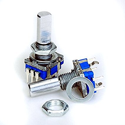
rotary encoder parts

$
0
0

hi all, I would need to use this type of rotary encoder for my project but I can not find this part anywhere online. Can someone help me? Thanks in advance
encoder

Where the DIAC on Fritzing

$
0
0

Hi, I do not need a specific model, with the generic one it would be perfect. I would greatly appreciate it.
diac_1

Viewing all 28578 articles
Browse latest View live


<script src="https://jsc.adskeeper.com/r/s/rssing.com.1596347.js" async> </script>