Everyone has kind-of left FZ now that an online version has been mentioned - even that has trouble attracting contributers -, so I would say if you need that you better switch to a different EDA. Basically FZ was designed for young people to get into electronics fast with a “monkey see monkey do” method, it’s just that people like the look and tried to push it into an advanced EDA.
Create a VCC Seed option
Mark groundfill seed pins as connected
Yeah you’re right, the status bar doesn’t update.
Creating a wire
Sorry, its for breadboard or streapboard.
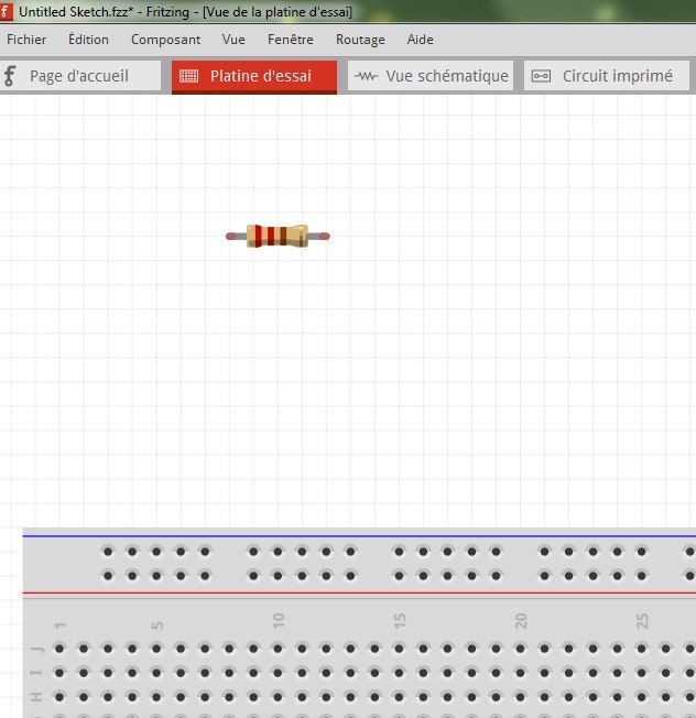
i know that i can use the junper wires, but they are too wide and hide the holes and components .
This in order to have a best visibility .
To substitute parts wiew
Excuse-me but i don’t understand very well …
Could you explain a little more … with a transistor for example
Create a VCC Seed option
So what is the “online” version that is as easy to use ?
I am particularly interested in the ability to construct board using a “breadboard” method of connecting readily available modules as well as loose parts.
Creating a wire
To substitute parts wiew
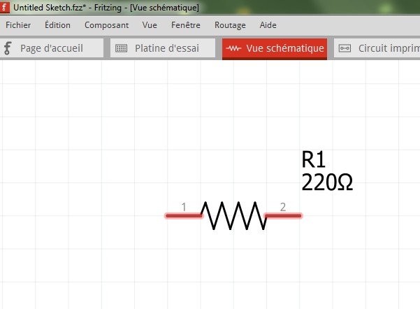
Right-click resistor in the Bin and select Edit Part, and File/Save as New Part
Go to SCH view, then select File/Show in Folder.
Right-click the highlighted resistor and copy and paste to another folder.
Go to Part Editor BB view and File/Load for View.
Check pin assignments and save.
Create a VCC Seed option
The online version hasn’t been made.
FZ is the only EDA with BB view, so you need it you have to use FZ.
Extras like a VCC plane will probably never be made, so we have to live with FZ the way it is.
Create a VCC Seed option
This is already possible in Fritzing albeit a little complicated.
- Remove all existing copper fill.
- Clear all ground fill seeds.
- Use the view from above/below button to view it from the side you want as ground.
- Use the top layer/both/bottom layer button to only allow work on the ground side.
- Set your ground seed.
- Ground fill top/bottom which ever side you are working on.
- Clear ground fill seeds.
- Switch view to the opposite side.
- Switch the top/both/bottom to the opposite side.
- Set the ground fill seed but this time select your vcc instead of ground
- Ground fill top/bottom which ever side you are working on.
- Clear ground fill seeds just to be safe so you can’t accidentally click ground fill.
Now you will have 2 filled side with different seed points.
Creating a wire
Yes , i see it’s better !
However it would be great if we could have the choice of the finer connections.
To substitute parts wiew
Thank you so much for this tutorial !
To substitute parts wiew
I am very disappointed, I tried the tutorial several times but without success.
I’m not very good …
Could you send me the piece if I give you my e-mail by Mp ?
(I know how to add a component in the store)
To substitute parts wiew
Post the .fzpz part here with the 7th button above and I will put the SCH in the BB view.
To substitute parts wiew
To substitute parts wiew
It wasn’t as easy as I thought, I had to copy SCH svg nodes to the BB svg.
Resistor_SCH-BB.fzpz (5.4 KB)
To substitute parts wiew
C’est super !
Congratulations, it’s exactely what i’m looking for !
How many time have you spend for creating this part ?
Do you think it’s possible for me also to built some others (like transistor, led, capacitor,diode … ) ?
To substitute parts wiew
If you know how to use a svg editor, ie Inkscape, it’s not hard, but if you don’t know, it is hard.
To substitute parts wiew
Ok, i don’t know how to use svg editor and Inkskape , only Photoshop 
I thought it was enough to change of place the data from one folder to another …
Never mind !
I’m happy to see that it’s possible to modify the icons BB like this , and perhaps other people will be interested by your work .
To substitute parts wiew
I think Photoshop is raster based drawing, where as FZ needs the very different vector based drawing. In theory you could draw with just lines of XML code.
Small Transformer 14x19x15h
I don’t know if anyone would want this because they seam to be non existent these days.
Small Transformer - 14mm sq core - 19mm wide - 15mm high - 2 Primary pins - 3 Secondary pins
v1 - Transformer.fzpz (8.8 KB)
EDIT - I moved this part here because the original was mainly talking about a LED Timing Light.


