If you know photoshop, you will find Adobe illustrator or Inkscape easy. The only hard thing is figuring out where are the common option at each program, like pencil, layers, etc.
To substitute parts wiew
To substitute parts wiew
I don’t feel able for this kind of realization because I don’t know enough English.
And google translation is not practical for tutorials or software.
This would be just for the most common components like capacitors, transistors, switches, LEDs, trimmers …
I hope someone will want to pursue the idea !
16x2 I2C LCD Part
Thank you so much for this. You literally saved me hours worth of work. Great contribution!
Create a VCC Seed option
it is also posssible via all copper fill, and then use traces to overlap you own desired-plane
I sometimes do that, but need to becareful.
using top-bottom to separated ground/Vcc is a good idea
Export creates distorted PCB
I made a PCB design and am trying to export it (RS-274X). However, for some reason the Gerber design becomes distorted when I submit it for production with Seeedstudio.
Image 1 - my original design in Fritzing
Image 2 - the resulting Gerber file, opened in Seeedstudio

What is this issue caused by? I tried resizing my PCB and moving components but the left side continues to be distorted. The board and both silkscreen layers I designed in Inkscape look perfectly fine.
Amplifying a 5V sq wave to 60V
Hi,
2n5551 is an NPN bipolar junction transistor (BJT). It is used in those projects where current controlling is required. In 2n5551 small current on base is used to control the large currents on emitter & collector. If you are working on 2n5551 then you should have a look at this tutorial Introduction to 2n5551. They have given detailed description of this BJT. I hope you will get some knowledge.
Thanks.
Export creates distorted PCB
EDIT: I redid my drawing in Inkscape, and gave it an extra few mm space on all sides, and it fixed the issue. Odd as this has never happened before.
Export creates distorted PCB
This is the result of Fritzing not understanding the PCB outline. You can often fix it by breaking apart your path in inkscape. Other times you need to convert the shape to a path and the last solution that has worked is to simplify your path inkscape.
Looking for an STM32 Blue Pill Part
I revised the BluePill as sugested and as it is useful to me I thought I would share it in case someone else might benefit.
This is revised as per Old Grey’s instructions above.
I am able to route both sides of the board.
Further for whatever reason I am no longer getting design check violations
So far it is working well for me.
BluePill.fzpz (882.1 KB)
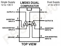
LM393N Dual Comparator Op Amp
The LM393N is an 8 pin ic chip.
It is commonly used in ADC converters, Comparison circuits, and wave-forms.

LM741 Single Operational amplifier
4116R-001-750 Inline resistor ic chip package
This ic chip contains 8 resistors which are isolated from each other.
The last 3 numbers designate the resistance.
The actual color of the Ic chip is a tan color.


Inline Resistor Network IC Chip.fzpz (6.7 KB)
Molex computer connector
I may be wrong, but it seems like the Molex 4 pin Computer Connectors are backward. Looking at the Male connector/female pin plug that comes from the power supply, with the flat side down and the top slide with slopes up, is that it goes 12V-N-N-5V. When I use the Sparkfun Molex Vertical connector, says 5V-N-N-12V. Am I missing something or is there an error?
Molex computer connector
Are you sure you are looking at the correct side of the board and are you thinking of looking at it from the correct side? It is easy to get mixed up that way.
Part image is visible in Editor but not Sketch
I imported the pin header from this post http://forum.fritzing.org/t/raspberry-pi-40pin-header/2108 into inkscape and added an .svg image with pin descriptions. I brought the resulting file into Fritzing Parts editor and it looked and acted as expected. But when using the part in a sketch the description image is not visible as in the screen shot below. I attempted to up load the file and screenshot but ,as a new user, can only upload one item so I could try to provide the file if necessary.
Part image is visible in Editor but not Sketch
Can you export the part from the parts bin in Fritzing and upload it here so we can have a look at it?
Part image is visible in Editor but not Sketch
I can give that a try, I believe this is it:RPi_GPIO_40_09381300504110b0527e243079598d72_5.fzp (23.2 KB)
I also have the .svg if necessary. I hope I got the right file as I made several attempts and the naming is a bit daunting…
Part image is visible in Editor but not Sketch
Unfortunately that is not the correct file. It is funny that everyone (including me the first time) look for the hidden file instead of right clicking on the part and pressing export which is what we need. The export will create a fzpz file which is just a zip file with all the svgs and the fzp file all together ready for import into another copy of Fritzing.
Part image is visible in Editor but not Sketch
Thanks, see if this is correct, thanks again.
Raspberry Pi Header 40pin.fzpz (326.3 KB)
Part image is visible in Editor but not Sketch
The image seems to be missing from the part. Can you upload the svg by itself?


