I just wanted to say what an amazing product fritzing is, and I hope that it continues to be updated and maintained. From my perspective, the UI is picture perfect. The only thing that I wish it could do is run a simulation – no minor task, I’m sure – but I’m just glad it’s around.
↧
In praise of fritzing!
↧
Schematic to breadboard layout
I’ve had a go at using the part you made. I can’t seem to get the right hand side pins to fit into the breadboard holes. Can’t line any of the wires up, or am I doing something wrong?
thanksChewie circuit.fzz (90.4 KB)
↧
↧
Schematic to breadboard layout
That is strange seeing as how I only changed the PCB image and left the other views as is.
But upon further inspection of the pictures I posted above I can now see that they are not connected in the original sketch and are the cause of the original warning. It looks like this pins are supposed to be ground pins. I would just draw a wire in breadboard view directly to your ground rail and ignore the fact they do not line up.
I do not use the breadboard view at all and never make svgs for breadboard so I can not be of much help in fixing the part to line up.
↧
Schematic to breadboard layout
I think the intention of FZ is, if it doesn’t fit in an actual BB, it won’t fit in a FZ BB. Like sub said run wires directly to the pins, and maybe even put the jacks OFF BB so you definitely know there is a connection to the pin and not a BB pin.
↧
Does an Arduino Uno Mega Shield SD Card ICSP SPI Exists Already?
Sorry for the late reply (I’ve been offline for 2 months with a broken ankle).
This is incorrect. The 74ahc125 (and it needs to be an 74ahc125 none of the others will work) should have VCC connected to 3.3V. When CS (pin2 on the 125) is at 5V the output to the sd card from pin3 (as an example) should be 3.3V. Checking this with a multimeter is a good bet, if the output to the SD card isn’t 3.3V something is wrong and the SD card may get damaged.
Peter
↧
↧
What is 2N4401 transistor
I think the simple answer is that you can’t. There are a number of things wrong with this circuit, starting with the connection of power to the 5V pin. The input power (greater than about 7 volts) should be going to VIN (assuming you don’t have the USB connected in which case the 5V is coming from the USB connection), the 5V pin is the output of a voltage regulator. You might be able to make a circuit where a PNP transistor connected across the power switch (assuming the power switch is a push button) was held on by writing a 0 to the D4 port. You would need to hold the switch down til the arduino boots and sets the port to 0 (and would need a resistor between the base of the transistor and the I/O pin to control the base current), but that won’t work if the USB is connected.
Peter
↧
Fritzing 0.9.3b "stopped working/responding"
Whenever i start fritzing it stops please refer image

my windows configuration is
Processor: intel® Core™ i% CPU M520 @ 2.40 GHz 2.40GHz
32 bit orperating system
Windows 7 professional
Please help
↧
Schematic to breadboard layout
Okay so I have connected it off the BB, this is how I have mine wired up physically. But I think that is wrong on fritzing? What do you think?
<a class=“attachment” <a class=“attachment” Chewie circuit.fzz (94.3 KB)
My sketch says I have 44 of 47 nets routed and 9 connections to be routed. I know the jacks have red dots on. But can that be fixed?
↧
Schematic to breadboard layout
I have had a go at the schematic view and managed to get most of the nets and routes connected. I am having a problem with the capacitors. They are connecting a bit strange, Would someone please check my current progress? I’m not sure if I have done it correctly. Thanks Chewie circuit.fzz (121.6 KB)
↧
↧
Fritzing 0.9.3b "stopped working/responding"
Is this a new installation or was it previously working and now doesn’t? The first (and least destructive) thing I would try is reinstall the Fritzing program from the zip file as this looks like some piece of code may be corrupted. After you do that, you need to wait (for possibly quite a while) while the parts database gets updated, during this process Fritzing appears to hang but if you interrupt it, then the parts data base will get corrupted and you need to try the next thing (which is destructive so make sure you have a backup first if you have sketches in Friting!):
There are two user directories (with your parts and the parts database) which don’t get touched during an install (to not affect your sketchs during upgrades). On Windows they are in
c:\users\username\AppData\Fritzing\roaming\Fritzing (which is a hidden directory so you need to enable hidden directories in explorer) and
c:\Users\username\My Documents\Fritzing (where username is your windows id)
If you don’t have any parts or sketches you want to keep you can just delete those two directories and Fritzing will receate them, or you can move them aside by renaming them if you wan to keep something in them.
Peter
↧
Schematic to breadboard layout
If that is how it is connected (and works) in real life then that’s also correct in Fritzing. The red dots only indicate no connection, since they aren’t being used that is fine here and isn’t your problem.
This looks to be caused by wires added (or incorrectly connected) in schematic and/or pcb. I’d suggest that you first move the parts in pcb (noting that many of you resistors are currently SMD which you may not want) so no pins overlap which makes routing (and not creating unintended connections) easier. You should do all the connections in one view (likely breadboard in this case) and once that is complete then follow the rats nest lines in schematic and pcb to make the routes the same. If you connect a wire incorrectly in schematic or pcb views that will reflect back in to breadboard view and break it. Sometimes (which may be the case here) this corrupts the sketch and you need to start again.
As noted above I’d suggest deleting all nets in schematic and pcb then work on breadboard til it is all routed and correct before moving on to schematic and pcb. In breadboard the wiring for the grey leds at the top looks to be incorrect. The data wire from the Arduino needs to go to din (not dout as it is now) on the other end of the module. As well you have a short from +5V to ground somewhere (probably in one of the other views) because if you click on a ground pin all the +5V pins also light yellow indicating they are connected together although breadboard looks correct to me. I think you may have a corrupted sketch (and thus need to start again). There are traces and vias in pcb view (which are likely wrong) but even when I removed all I could find it still says there are two nets routed (which there shouldn’t be).
Peter
↧
3-Axis Compass GY-271 QMC5883L
Sorry for the late reply, I have been offline for a couple of months with a broken ankle. The part check script is a python script (available on github) that checks the xml of a part against the parts file format document and reports errors. It isn’t all that easy to use if you aren’t familiar with what a correct part should look like. In the case of your part it (and I) find a number of errors. The svgs are missing layerIds. If the layerid in the svg doesn’t match the fzp file then pdf and svg export on Fritzing don’t work. Breadboard has termanalId specified in the fzp file but not the svg (this doesn’t really affect anything in breadboard), and the same in schematic where it does matter. As well it is desirable to have the outline of the board (so the area it takes up on the pcb is visable during layout) as a silkscreen layer in the pcb svg. This image shows the problems in the schematic svg:
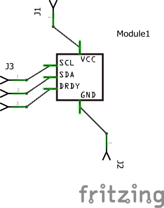
The connection to the middle of the pin (rather than the end which is desirable) is caused by the missing terminalId. I use a 10 thou by 10 thou rectangle labeled connectorxterminal
(where x is 0 to 4 depending on the pin number in this case) aligned to the end of the pin. As well your part isn’t aligned on .1 in boundaries so it doesn’t match with other parts.
Peter
↧
My custom part causing Fritzing to crash on PCB check
One cause of this is a bug in Fritzing where loading an invalid part isn’t correctly dealt with which hangs Fritzing and corrupts the parts database. I have what I think is a fix for this, but need to get bask to working on being able to build Fritzing for Windows (the fix works on Linux) to test it more.
I downloaded and tried your part (I keep backup copies of the database files in case of corruption  ) and had no problems. The default drc rules complain about clearances and your part isn’t correct (the holes don’t get drilled in the gerber output probably because the pads aren’t defined correctly though I haven’t looked), but it does not crash Fritzing for me (9.3.b on Win7). If you like I can correct the pcb svg so if will generate correct gerber output. As Old_Grey said if you upload the fzz file for the sketch one of us can see if we can figure out why Fritzing crashes, assuming it does for us.
Peter
↧
↧
Schematic to breadboard layout
Yay Van, you’re back.
Tip for SCH view - I don’t like traces on traces with junctions in the wrong place, because that can lead to mistakes because you can’t see the actual connection, ie if you have 4 resistors connected in pairs. but the traces overlap. you may think all 4 are connected but aren’t in real life. Look at LED4, it has a pin touching a trace but it’s not connected - grab the LED4 part and move it and you will see what is really happening.
The correct way to do junctions is to right-click the trace and add bendpoint, or just grab the trace and move it and put it back, then run the other trace to that point, or hold ALT and make a trace from the bendpoint out. Always grab the junction after you have it connected and move it, checking all 3 traces move with it - 4 junctions don’t all move at once because there is a bug -.
↧
Is there a bug in 0.9.3b?
Not ready to use. I know it’s free and I appreciate that. Why can’t we just import a .fzpz that can land in the “My Parts” lib?
↧
Is there a bug in 0.9.3b?
You can. In the top right corner of the parts menu there is a hamburger icon that opens a menu with an import function.
↧
Schematic to breadboard layout
Your breadboard view is incorrect and I don’t know enough about the circuit to fix it. However I did fix up pcb and schematic views where fix up means deleted all wires in both views and rearrange the parts in a semi sensible layout in pcb. Note I changed all the SMD resistors to through hole to match breadboard (you can change them back to smd with inspector if you really wanted smd). Some of your problems were wires connected (probably incorrectly) in pcb view. The way forward from this sketch is to correct the errors in breadboard view:
-
I changed the wires so the connections more easily followed because they don’t overlap one another. This a bit of work but reduces wiring errors and is thus worthwhile. You need to check the green wire on pin1 txd is correct as it was also connected to one of the yellow wires going to the jacks which I expect was wrong.
-
The wire to dout on the neopixel strip should be going to din not dout. At the same time I simplified the power connections.
-
The 6n137 optocoupler is wrong and I don’t know how to fix it. As it stands it will not do anything as the diode (if it is supposed to be driving whatever is on din2) will be always on. I expect there should be an output from the Mega that should drive the diode (if it is intended to be driving whatever is on din2) which is not present. If you can provide the circuit or device that connects to dini2 I can possibly figure out how this should be connected. Once breadboard is corrected then we can move on to moving the parts around in schematic and making the necessary connections, but first we need to get breadboard correct. The sketch below is how I would lay out breadboard (with as noted the 6n137 not being correct). However as it is still showing 2 nets routed in pcb view despite no wires being connected and 7 unrouted connections in breadboard (but no unrouted nets when the message is clicked) I expect the sketch is corrupted and you will need to start a new sketch and recreate this sketch starting in breadboard (leaving pcb and schematic totally alone) to make ti work once we figure out how the optocoupler should be connected.
Chewie circuit_start.fzz (93.5 KB)
Peter
↧
↧
Is there a bug in 0.9.3b?
Or click file->open, browse to the fzpz file and click on it. Assuming it is a valid part it will load in to the my parts bin ready for use. If it is an invalid part, a Fritzing bug will cause a hang and require the parts database and all your sketches to be cleared (so it is a good idea to keep a backup of the two user directories before loading unknown parts).
Peter
↧
Schematic to breadboard layout
Thank you for taking time to look at my fritzing sketch, and correcting a lot of things. I should explain what my circuit does. It is a midi controller, I am using it as a loop pedal. the leds light depending on what mode the controller is currently in. It has 10 pedals, a neopixel ring, led strip, 6 common cathode leds, a potentiometer and midi in and out.
Yeah I placed the incorrect resistors on my circuit. They should of just been standard resistors. The pin 1TX is correct that’s what it should be connected to. My bad I didn’t notice I wired up the neo peixel ring wrong. The 6n138 optocoupler is wrong anyway, it is the wrong value it needs to be a 1n914. But I was unable to find one in fritzing, I need to make one in the parts editor but I don’t know how to do that. Same with the diode, it needs to be a 1n914 diode. With the optocoupler like you said it needs a wire from the arduino to drive it. There needs to be a connection from pin 6 on the optocoupler to pin 0RX on the arduino. Here is the circuit http://www.notesandvolts.com/2015/02/midi-and-arduino-build-midi-input.html
I have two 1000uf capacitors on my circuit they are supoused to be for the neo pixel ring and the led strip. Couldn’t I not just use one connected across the power rails of the neo pixel ring and the led strip? I will now begin a new sketch as you said.
Thank you
↧
Schematic to breadboard layout
I have fully redrawn my breadboard from scratch like you said but I think I may have ran into the bug again. My sketch says “49 out of 50 nets routed” and “6 connections still to be routed”. I hope I haven’t ran into the bug because spent hours on this redrawing it. I also noticed I had my diode pointing the wrong way the negative line on the diode needs to be facing to the right. So i have flipped that around so it is correct. I have moved the parts in the schematic view and pcb view but didn’t quite get around to finishing the pcb view . Here is my new sketch showing the current progress. Thank you all for your help Chewie 2.fzz (86.6 KB)
↧