Quantcast
Channel: fritzing forum - Latest posts
Viewing all 30948 articles
Browse latest View live

Positioning the Arduino headers on a PCB board

$
0
0

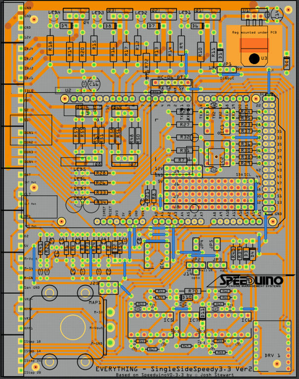
Ah! my mistake then, I figured you already had edited a part (which is what you will need to do to make a shield part). Your life just got a lot more complicated because you are descending in to parts creation hell :slight_smile: . It is poorly documented and complex, but several of us are happy to help. Which Arduino are you targeting, because we already have shield templates for some of them? In fact if you type shield in to the parts search (the magnifying glass on the parts bin in the right hand window) they will all come up (along with a lot of non relevant parts because search is more than a bit odd :slight_smile: ). There are templates for the uno and mega there and maybe others. The icons with pcb traces are usually the shield templates. Here are a couple of tutorials (that apply to the current fritzing version which most do not) on parts making. You probably want Old_grey’s video series, it is more complete and more recently updated them mine.

Peter


Conception de 2 circuits imprimés avec capteurs à effet hall , et une carte arduino , pour un accordéon

$
0
0

merci pour votre réponse . Mais je ne sais pas faire d’esquisse . Ce n’est pas moi qui est fait le schéma de principe . Les capteurs ne seront pas tous droit , il peuvent être soudés un peu en biais car il y a des décalages ou alors il faut réduire un peu le percage à - de 2.54 .rampe capteur accordéonUntitled Sketch.fzz (46.5 KB)
ce n’est pas complet et je ne sais pas faire j’ai juste installé l’application fritzing il y a 2 jours !!!

sorry

74LS IC's i need help for these parts

Positioning the Arduino headers on a PCB board

$
0
0

Are you saying that you have positioned parts in the PCB view, if it is then upload the sketch, ie the .fzz.

240V ac power supply source and a bulb

Positioning the Arduino headers on a PCB board

$
0
0

OK - here is the .fzz

I have not used the std arduino shield as I am running a ton of traces thru the two IC’s and on to 4 Ethernet plugs going to the leds I am driving.

I will be supplying external 12v to the UNO and the regulated 5v to the two IC’s. there are a total of 8 sets of 3 leds and only one led in each set will be on at any time.

To repeat - my issue right now is to be sure the headers for the UNO that I have positioned on the new PCB are in the exact correct place to plug into the UNO & my reading of the Jx position would tell me that the headers (might) be off by a few thousandths (??)
PCB-Arduino shield base - V9 Power bus.fzz (30.0 KB)

thx

Conception de 2 circuits imprimés avec capteurs à effet hall , et une carte arduino , pour un accordéon

Conception de 2 circuits imprimés avec capteurs à effet hall , et une carte arduino , pour un accordéon

$
0
0

I kind-of felt that he wanted help making a sketch in FZ.

If you want to use BB view as the master for connections - most people use SCH view -, you must make the BB view correct.

Wires touching in BB view are not connected. If you click on green pin F8 on the first BB the pin holes turn yellow. Now look at pin F4, it is not yellow. These 2 wires are not connected.

Si vous souhaitez utiliser la vue BB en tant que maître pour les connexions (la plupart des gens utilisent la vue SCH), vous devez corriger la vue BB.

Les fils se touchant dans la vue BB ne sont pas connectés. Si vous cliquez sur la broche verte F8 sur le premier BB, les trous pour les broches deviennent jaunes. Regardez maintenant la broche F4, elle n’est pas jaune. Ces 2 fils ne sont pas connectés.

There are youtube tutorials, maybe some are subtitled in French.
Il existe des tutoriels youtube, certains sont peut-être sous-titrés en français.

EDIT - I just found out there is no Hall sensor in FZ, but then again he might need one with 2mm spacing.


Positioning the Arduino headers on a PCB board

$
0
0

They look pretty close - I can see slight non concentricity -, but it should be fine because the tolerance of the holes will allow for some movement. The double check is to print out the gerber and see if the part fits exactly on it.

The usual way to do this is to use an actual UNO and leave it there.

On a side note you might want to brush up on bendpoint junctions. If you click on Pin8 on U3 you will see pin8 on U1 doesn’t turn yellow, so they are not connected. What you do is grab a wire and move it and put it back, and that creates a bendpoint. Then run a wire to that BP, or hold ALT and click on the BP and run a wire to the pin. You can also right-click on a wire and make a BP. Basically things touching doesn’t means they are connected, but using BP junctions can tell you they are connected.

240V ac power supply source and a lamp

$
0
0

New to Fritzing but hooked. I am doing a smart bulb project and I am using fritzing for my circuit design but l could not find a 240V ac power supply source and a bulb. Can anyone help me with that please. The picture is not pretty clear but tha is what I am looking for.

240V ac power supply source and a bulb

Positioning the Arduino headers on a PCB board

$
0
0

Thx

I’m surprised I cannot use the location of each header to precisely position the parts - ? I would have thought a set of 4 co-ordinates for each of the required headers would ensure no problems.

I have positioned them by placing an Arduino shield (sent to back) and visually checking like you have done. Then deleting it.

I’ll be interested to see what Peter has to say about suing co-ordinates.

thanks for your help - I just fixed the power traces - good deal.

Positioning the Arduino headers on a PCB board

$
0
0

I think the coords in FZ only has a 4 or 6 thou resolution, hence why it jumps when you enter numbers.

Everybody usually leaves the Arduino on the board even though it’s not part of a shied.

EDIT - Actually if you know how to edit parts at the svg level you can remove the silkscreen of the UNO.

Positioning the Arduino headers on a PCB board

$
0
0

Old_Grey is a better bet on board issues than me. I rarely do boards. My normal method of setting coords is to edit the underlying svg file rather than using Fritzing. As Old_Grey noted the real test is to create the gerber files (yet another conversion inside of Fritzing) and check the position there with a viewer such as gerbv. The gerber output is what the board house will use to produce the boards and is thus the final answer to position questions. As suggested I’d print a copy of the gerber output at 1 to 1 scale on to a transparent sheet used to make projector slides and place it over your Arduino. If those holes match up you are golden.

Peter

Positioning the Arduino headers on a PCB board

$
0
0

OK - all good points. I will try the gerber files and proceed from there.

appreciate the help


Conception de 2 circuits imprimés avec capteurs à effet hall , et une carte arduino , pour un accordéon

$
0
0

The first thing we needed is a proper part for the sensor (thanks for the data sheet!), so I made one.

A3144 Hall Effect Sensor_.fzpz (6.7 KB)

It is on .05 in centers and 4.17mm wide.

Now we need to know the desired distance between the two red lines (i.e. the spacing between the hall effect sensors on the pcb) in inches or mm and we should be able to do this.

distance

Peter

Drawing Resource - Alternative to Inkscape

$
0
0

I often use OP-Amp’s - usually LM358, MCP6002 and MC1458.

These are DIP8’s with similar Pinouts and Performance.

Most of the time, I use only one Channel, thus I made a Part without the 3-unused pins.

This provides extra space for routing…

I spent a good amount of time discovering the tricks to using Gravit Designer and, while it has some gotcha’s, it is an absolutely perfect fit for my Fritzing Part and PCB making! Just need to learn the tricks and, perhaps best of all, it provides for Pages and Masters…

So, here’s what I did:

Created a single Part document that contains Pages for:
Schematic
PCB
Breadboard
Icon

Each has it’s Layers and Elements as required by Fritzing.

Exporting with One-Click saved all Pages to individual SVG files as needed for Fritzing.

Used BBedit as a Text-Editor to delete the lines in XML that caused problem (until they fix that).

FYI - you can use any text-editor on XML, just select the file and ‘Open-With’ the text-editor, as double clicking opens SVG in default program.

Attached are:
Screenshots
OP-Amp Part file
PCB file
Fritzing file

Other than deleting the Vector-Scaling text (until they fix that) I did NOT need to do any XML editing.
Also, though with Inkscape, I had to make Paths, I did not make anything into a Path for this (though, I think I left the file with a Path for the text but, it wasn’t needed)… sooo cool :joy: All contents are as natively created in Gravit.

Notice there is a Cutout in the PCB. Simple!

For those interested in Gravit, the Part and PCB files are attached - BE SURE to Delete the .fzz

Hopefully the file (done on a Mac) will open in the Window/Linux and other platform versions…
Yes, I like Big contact pads and set the DRC to 0.2mm. I use 1mm diam holes to minimize changing bits on my CNC mil.

Baseline_1_OP-AMP.gvdesign.fzz (36.0 KB)
PCB_1_Baseline2.gvdesign.fzz (35.2 KB)
OP-AMP DIP8.fzpz (9.1 KB)

1 of 2 nets routed

$
0
0

Thank you for the help. I feel relieved now.
Thanks for this tip!
Sorry for my late response.
I appreciate your gesture and support for me.

Conception de 2 circuits imprimés avec capteurs à effet hall , et une carte arduino , pour un accordéon

$
0
0

It’s a bit hard to follow what’s going on because the translation isn’t great, but I think we need the spacing of the magnets. Then again there is a thing with switches.

I read 305mm, then something 335mm, it all gets confusing. We really need a mech drawing.

Conception de 2 circuits imprimés avec capteurs à effet hall , et une carte arduino , pour un accordéon

$
0
0

305m is the max size of the board, it is going in to a space that is 335mm long as I read it. The extra space has something else in it I assume. I’m redoing the small signal diodes I did a couple of years ago because they are needed here, then I’ll try a minimum space board with 49 hall effect sensors and see how long that is.

Peter

Viewing all 30948 articles
Browse latest View live


<script src="https://jsc.adskeeper.com/r/s/rssing.com.1596347.js" async> </script>