Quantcast
Channel: fritzing forum - Latest posts
Viewing all 30956 articles
Browse latest View live

1 of 2 nets routed

$
0
0

not a problem, we just go on to other things until someone brings the topic up again. Sometimes it is months between replies in these threads :slight_smile: . We are patient. This is an odd one because I could swear this used to work (and it should work) but I can’ now find an example where it used to work, the common cases (connections between modules) do work and this case may not have come up before. There are rules about connections in breadboard (except for wires which will connect anything to anything, connections must be male to female or female to male for instance). This case however is wires and unless there are rules I don’t know about (always possible because little of this stuff is actually documented except in the source) there is a bug which is worth knowing.

Peter


Conception de 2 circuits imprimés avec capteurs à effet hall , et une carte arduino , pour un accordéon

$
0
0

OK, I did about 25 (a bit more than half) of the sensors on a 30cm by 3CM PCB. With half done we are using less than half the board space so fitting 49 sensors in to 30Cm shouldn’t be a problem. It is currently late here so I’ll continue this tomorrow. If you can supply the desired spacing between sensors it is easy to move the sensors in to the position you want them (and the leads will allow you to adjust them one way or the other for a short distance as well.)

here is the sketch with half the sensors done:

accordion-Sketch.fzz (42.6 KB)

Peter

Conception de 2 circuits imprimés avec capteurs à effet hall , et une carte arduino , pour un accordéon

$
0
0

You can box 1 BB of parts - you have to start the box in a blank area and not on the BB -, hold CTRL and click on the BB to deselect it, and then just copy paste and move that block of parts. If you want the parts in the other views to move in an orderly pattern you have to line the parts in a row, which you have done, and it will copy the parts in a row in the other views when you copy the BB parts.

I don’t know if the Hall SCH is the best for packing 49 parts in a row, maybe something more compact.

I personally wouldn’t even do a BB view, only a SCH and PCB, because it just seams like more work for something that will not be made in real life.

240V ac power supply source and a bulb

$
0
0

Thanks for your reply vanepp.
I went to the link you provided but could not get any parts to download there. It is basically a page explaining how to complete a project similar to the one I am doing. I have tried google to but nothing seems to come up for 240V ac power supply source or the light bulb!

240V ac power supply source and a bulb

$
0
0

Just to say I got the light bulb from the link below. Still looking for 240V ac power source though.

Deleting Fritzing account/profile permanently

$
0
0

Hello there,

I want to delete my Fritzing account/profile permanently. So, how can i do that?

240V ac power supply source and a bulb

$
0
0

In the top right corner (I had to scroll the page right to see it) there is a download files page which has a Fritzing.fzz file. That file in the temp parts bin has the bulb and a 220V socket used to power it.

Peter

Conception de 2 circuits imprimés avec capteurs à effet hall , et une carte arduino , pour un accordéon

$
0
0

Wish I’d read that before finishing this :frowning: , I tried selecting a bunch and copying but was on bb and didn’t use cntrl and it didn’t work so I did it manually.
Peter


Drawing Resource - Alternative to Inkscape

$
0
0

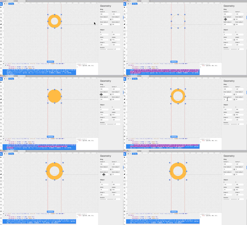
To complete this post, Just and FYI…

Although Boxy is for Mac (and Windows10), I wanted to post an image of the GUI showing the XML editor and Layer (objects) panel.

It’s very clean/uncluttered. Very usable for making Fritzing parts.

There are no issues importing into Fritzing (like the vector-sizing issue with Gravit).

EDIT: One of the pains (for me) using Inkscape is to size contact pads. In a common-sense way, it would be nice to set the inner and outer diameter as desired without needing to fuss with boxsize and stroke width and iterate them as one affects the other.

Boxy takes care of that by having an Inner and Outer value box for the Ring… just using the scroll wheel in the box takes care of it :grinning:

mov

Conception de 2 circuits imprimés avec capteurs à effet hall , et une carte arduino , pour un accordéon

$
0
0

OK looks like it will fit fine, here is the complete 49 sensors on a 30CM wide pcb at minimum spacing:

as you see we have room at the end if needed. So to go forward I need to know what spacing between the sensors you would like and how the 8 connections to the mega are made. The choices would look to be a 8 pin header (which provides either holes for wires or a header to plug a cable in to, or an 8 pin dual row header to take an 8 conductor IDC ribbon connector cable. Which would you prefer? Also where do you want the connector, left end, right end, middle of the board or somewhere else. All the parts need to be placed before routing the pcb. Does anything else (such as the switches in the schematic) need to go on this board as well or is it only the hall sensors and the diodes.?

Peter

Conception de 2 circuits imprimés avec capteurs à effet hall , et une carte arduino , pour un accordéon

$
0
0

Bonjour peter , je vous joint une photo; Sur cette photo il y a la photo de mon circuit left hand du capteur de 1 à 49 sur 300 mm exactly with the hall effect sensor just in face of the black trait on the white réglette this is my matrice because every 49 magnet are stick on la soupape do do # ré # mi …look the second photo . For les wires , look the schéma tom scarff vers la arduino mega 23 25 27 29 31 33 35 37 39 22 … with X2 : 32 30 26 24 22 pontés entre eux and for push button 4 . I think qu 'il faudrait un connecteur au centre de la carte qui reprenne le maximum de wires en nappe sauf les interrupteurs et la broche midi . thank you peter

Conception de 2 circuits imprimés avec capteurs à effet hall , et une carte arduino , pour un accordéon

Conception de 2 circuits imprimés avec capteurs à effet hall , et une carte arduino , pour un accordéon

$
0
0

Merci peter pour votre aide , je ne sais pas choisir le type de connection ,le brochage ,

Les diodes D1 à D6 reliées au fil 23
les diodes D7 à D12 reliées au fil 25 …

il y a environ 35 wires
à souder sur la carte arduino 2560

Conception de 2 circuits imprimés avec capteurs à effet hall , et une carte arduino , pour un accordéon

$
0
0

Is it 300mm or 305mm from the centre of magnet 1 to the centre of magnet 49. The measurement has to be exact.

Est-ce 300 ou 305 mm du centre de l’aimant 1 au centre de l’aimant 49. La mesure doit être exacte.

Conception de 2 circuits imprimés avec capteurs à effet hall , et une carte arduino , pour un accordéon

$
0
0

Bonsoir, c’est très difficile de vous donner une mesure exacte la seule mesure exact elle est entre la
1 ière tige et la 49 ième tige . Je vous envoie un petit croquis merci pour votre aide philippe


Conception de 2 circuits imprimés avec capteurs à effet hall , et une carte arduino , pour un accordéon

$
0
0

Je pense qu’en prenant la pin 2 du capteur à effet hall comme repère avec mon croquis on à pour la main droite 6 mm et pour la main gauche 7 mm entre les capteurs . Mais supports pour les magnets , les tiges ne sont pas exactely à la même distance .


thank you

Conception de 2 circuits imprimés avec capteurs à effet hall , et une carte arduino , pour un accordéon

$
0
0

I’m a bit confused because 49 Hall sensors at 7mm is 336mm, but the gap between posts is only 300mm.

Right-hand is 288mm from pin 2 of #1 A3144 - to pin 2 of #49, so is ok.

Conception de 2 circuits imprimés avec capteurs à effet hall , et une carte arduino , pour un accordéon

$
0
0

305 mm du centre de l’aimant ça me semble très correct merci peter

Conception de 2 circuits imprimés avec capteurs à effet hall , et une carte arduino , pour un accordéon

$
0
0

eh oui je ne comprenais pas moi non plus !!! avec un espacement à 2.54 mm !!! je vais me coucher merci

Conception de 2 circuits imprimés avec capteurs à effet hall , et une carte arduino , pour un accordéon

$
0
0

I suspect we don’t need exact measurements except for the maximum length of the board. It is just that if some particular pattern would make it easier to do, before the board is layed out is time to do that. I’ll space the sensor pads out across the length of the board. With long leads on the sensors you should be able to tilt them a bit one way or the other before soldering them to fit them where they need to go. it should also be possible to make both a dual row header (looks like about 20 pins all told) and a row of single pads at the back / center of the board so you can use either ribbon cable or wires, which ever works best. All the internal wiring will be traces on the circuit board so it is only the connections to the mega (and power and ground which don’t show on the initial schematic) that need pads.

Peter

Viewing all 30956 articles
Browse latest View live


<script src="https://jsc.adskeeper.com/r/s/rssing.com.1596347.js" async> </script>