The Gcode files are generated from CopperCam (using Gerbers exported from Fritzing).
CopperCam is a Windows only program.
Having only a Mac, I’ve used VirtualBox for years so, it was natural to use it for CopperCam. But,
recently, I completely rebuilt the Mac/OSX and did not bother to install VirtualBox.
To run CopperCam, I installed “WineBottler” and “Wine”. My Goodness, what slick approach!
There are different versions of Wine & Bottler, I picked this one as it was Free and isn’t wrapped by one’s having Ad’s (such as by ‘CodeWarriors’). Wine/Bottler versions for Linux are available.
Wine/Bottler installed easily/quickly and installing CopperCam was just as easy!
Wine has two options to run the Bottled app:
One) can run a Windows program (Directly) at click of button.
Two) can create a Mac-based app/package with a specified/desired Windows version.
Both worked but ‘One’ is a no-brainer to setup. All that’s needed after installing Wine, is to Double-Click the desired Window program, such as CopperCam.exe and select Run Directly. If digging into files, a ‘C: Drive’ gets created and is usable from the Mac, too.
(Another Windows program I needed required ‘framework .NET’ so, option ‘Two’ was needed as it enables picking from a long list of add-in features (called WineTricks)… All the versions of .NET are there.
Hello. I’m begginer with this desing software. I need to make a project, and I don’t found this component in Fritzing. I need this slide switch with 4 pins(SS-13D01.). I don’t know to make this component, can anybody help me, please. Thank you.
There is plenty of information to make a part and I will do so in a while (maybe a longish while, because I see square holes and I may need to enlist @opera_night’s help I have yet to be able to make square holes work ). The next problem is schematic. There are 4 physical pins spaced like this:
1 2 3 4 5
0 0 0 0
and from the shorting I expect that 2 pins short at each position, but the schematic seems to have 5 pins and I’m unclear which is which and how they relate. I think it may be 3 position, in position a (fully to the right) pin 5 shorts to pin 3, one position left seems to be off, with a connection to pin 2 which does nothing (and why do we have pin 2?) and one more left shorts pins 1 and 3. Does that match how the switch actually works? It seems unlikely because then pin 2 is useless and that doesn’t seem correct.
I know that I can change the color of an LED. I also would like to change the size that appears on the screen because it is so large that is covering the resistor right behind it. Can that be done? Thanks.
Only by using a different led part that is smaller. If you click on the led in breadboard, then look in Inspector, (bottom right of the screen) you can change the default 5mm LED to a 3mm led in the package field and the led will get smaller in breadboard (it is actually loading a different part). There are also alternate (not in core parts) leds, square that are designed to fit between .1 centers. Depends what you want / are willing to accept. I or one of the other part makers can also cut down the size of a standard led.
OK try this part and see if it does better. There are a variety of problems in your original part. Breadboard is fine, pcb is missing the copper0 layer so thinks it is a surface mount part and will only make connections on the top layer. It also had a translate which I suspect is the source of your clearance problems. Schematic has the most visible changes. I expect you ran it through Parts Editor twice, which has the effect (if you don’t remove the px from font-sizes) of setting the font size to 0 thus the small text in schematic. I also added a label for the part (remove it from the svg if you don’t want it.) This is a new part (I changed the moduleId so it will load along side your original part for comparison.
note in your part on the left all connections are on the top layer because of no copper0 layer in the pcb svg against connections on both layers on the new part on the right. As well in both parts the hole size is 0.035in. Normally for .1 square headers the hole size is 0.038in. If you would like to change that the easy way is edit the pcb svg in a text editor and do a global replace of r=“27.5” with r=“29” which will change the hole size from 0.035 to 0.038in leaving the circle in the same place. As well the mounting holes are in silkscreen. This means that if you make boards, the holes will appear on the silkscreen but not be drilled. This is normal practice for Fritzing (which you may be aware of) and if you want the mounting holes drilled, you drag a hole from the core parts bin in to pcb view and set its size appropriately. It is also possible by changing the pcb svg to always drill the holes (but then someone that doesn’t want the mounting holes drilled needs to change the part to do that, unlike with the hole position in silkscreen.) On to schematic:
Here your original part is on the top and the labels are too small to read. My part is on the bottom with properly sized labels and a label field telling us what the module is. Hope this helps! If this doesn’t fix you clearance problems you will need to upload the sketch so I can see the problem and try and figure out what is causing it.
Peter
via google translate:
OK, versuchen Sie dieses Teil und sehen Sie, ob es besser tut. Es gibt eine Vielzahl von Problemen in Ihrem Originalteil. Das Steckbrett ist in Ordnung, der Leiterplatte fehlt die Kupferschicht 0, daher wird angenommen, dass es sich um ein oberflächenmontiertes Teil handelt, und es werden nur Verbindungen auf der obersten Schicht hergestellt. Es gab auch eine Übersetzung, von der ich vermute, dass sie die Ursache für Ihre Freigabeprobleme ist. Schema hat die sichtbarsten Änderungen. Ich gehe davon aus, dass Sie den Teile-Editor zweimal durchlaufen haben, was zur Folge hat (wenn Sie die Pixel nicht aus den Schriftgrößen entfernen), dass die Schriftgröße auf 0 gesetzt wird, also der kleine Text im Schaltplan. Ich habe auch eine Beschriftung für das Teil hinzugefügt (entfernen Sie es aus dem SVG, wenn Sie es nicht wollen.) Dies ist ein neues Teil (ich habe die Modul-ID geändert, damit es zum Vergleich neben Ihrem Originalteil geladen wird.
Einige Screenshots mit den Änderungen:
pcb
Beachten Sie in Ihrem Teil auf der linken Seite, dass sich alle Verbindungen auf der obersten Ebene befinden, da in der Leiterplatten-SVG keine Kupfer0-Ebene vorhanden ist, gegenüber Verbindungen auf beiden Ebenen auf dem neuen Teil auf der rechten Seite. Auch in beiden Teilen beträgt die Lochgröße 0,035 Zoll. Normalerweise beträgt die Lochgröße für Überschriften mit 0,1 Quadratmetern 0,038 Zoll. Wenn Sie dies auf einfache Weise ändern möchten, bearbeiten Sie die Datei pcb svg in einem Texteditor und ersetzen Sie r = “27.5” durch r = “29”, wodurch sich die Lochgröße von 0,035 auf 0,038 ändert, wenn Sie den Kreis verlassen am gleichen Ort. Die Befestigungslöcher befinden sich ebenfalls im Siebdruck. Wenn Sie also Bretter herstellen, erscheinen die Löcher auf dem Siebdruck, werden jedoch nicht gebohrt. Dies ist die übliche Vorgehensweise bei Fritzing (die Sie möglicherweise kennen). Wenn Sie die Montagelöcher bohren möchten, ziehen Sie ein Loch aus dem Kernteilefach in die Leiterplattenansicht und stellen Sie dessen Größe entsprechend ein. Es ist auch möglich, durch Ändern der PCB Svg immer die Löcher zu bohren (aber dann muss jemand, der die gebohrten Befestigungslöcher nicht will, das Teil ändern, um dies zu tun, im Gegensatz zu der Lochposition im Siebdruck.) Weiter zum Schaltplan:
Hier befindet sich Ihr Originalteil oben und die Etiketten sind zu klein zum Lesen. Mein Teil ist unten mit richtig großen Beschriftungen und einem Beschriftungsfeld, das uns sagt, was das Modul ist. Hoffe das hilft! Wenn sich das Problem dadurch nicht beheben lässt, müssen Sie die Skizze hochladen, damit ich das Problem sehen und herausfinden kann, was es verursacht.
Thank you so much. One question, I found in this forum an layout for 8 pin socket for integrated components(4 with 4 for lm386)? I search and I don’t found.
I don’t see a post about the lm386, but there is a part in core parts. If you start fritzing and in the right hand top window (Parts) in the search window (the magnifying glass icon), type lm386 and press enter (a mouse click doesn’t work) the lm386 part will come up.
Those holes are for mounting. (the part has Metal Tabs). Nearly all PCB’s receiving this type of feature use Round Holes. The ‘Rectangle’ in the layout is the Boundry of the Tab - the tab is not uniform shape.
Therefore, just grab the ‘Hole’ part and set the Ring Thickness = 0, and the Hole Diameter to 1.2mm.
Most all of the slide switches I use have some version of these tabs, they can be bent over to hold switch on the PCB to reduce the Force of Handling/sliding On/Off.
Sometimes I bend them such that they sit flat on top of the PCB (depends on the project).
Otherwise, a custom PCB with cutouts is needed…
Oh, you may not want this but, I posted my version of LM386 along with some images of Actual Amplifier (scroll down this page)
It turns out that making a contact pad with a Rectangular cutout is very easy.
In previous post’s I referred to making simple cutouts using SVG’s ‘intrinsic’ ability to ‘Difference’ elements.
Example (the SVG):
I created the usual two layers; copper0 & copper1
I created a filled circle.
I created a Rectangle by drawing 4 bizer lines in a CounterClockwise direction (that’s the key to intrinsic Differencing).
I first selected the Circle then, the Rectangle and Differenced them (thus ending with a Differenced Path).
To test this:
I used a core part (an Antenna). I was not concerned with the Schematic/Breadboard/Icon.
I placed three of them on a PCB.
Also, I dragged two “Copper Image’ parts onto the PCB.
I stretched one of the Image parts to enlarge it.
I exported Gerbers.
I loaded them into CopperCam.
Results: It works! NOTE: Of course, you can’t drill a Square Hole but, you can Mill and Laser it. The resulting Gerbers are enough to enable this via setting them as Contours when setting up the machining files.
I made the attached PCB File for those wanting Cutouts on the PCB for whatever reasons (including features for Parts) and Not wanting to fuss around, learning, installing software… )
It’s pretty simple:
Example:
Know (approx) what PCB dimensions you want.
Start a New Fritzing Sketch.
Click the PCB and Load the PCB_4_Cutouts.SVG from the Inspector Panel.
Resize the PCB as needed to your required dimensions (don’t worry about the existing cutout - you’ll tweak).
Add your design/parts/etc. Layout as close to final as possible.
Edit the PCB_4_Cutouts.SVG in your favorite Graphics Program. Move, Re-Size, Copy and Paste existing Cutouts or Add/create new ones as needed…
Export/Save the file.
Reload it into Fritzing and confirm all is well.
Done * Your Exported Gerbers should be good for Laser cutting and Milling the board’s Contour with Cutouts.
The file PCB_4_Cutouts.SVG has:
Two Rectangles and One Bezigon Line Shaped cutouts.
A Silkscreen layer with Board Shape (offset) and One Rectangle around a cutout for the Silkscreen.
Tweak as needed/indicated above…
Results - Images below:
Fritzing Sketch with example and Milled simulation (CopperCam)
Gerbers of Board Contour and Btm Copper Layer
NOTE: I did not Horizontally flip the board for milling - would normally do that but was lazy for this post.
So I had my first PCB fabricated, a simple breakout board for the AD5206 digital potentiometer. I used a readily available Fritzing part that had an SMD variant, and I thought all was good. However, when both the chips and the PCBs arrived yesterday, I found that the chip is slightly wider than the part footprint on the board. (Reference photos below.)
The part footprint on the PCB has a spacing of 4mm between the pads, but the connectors on my chip have an inside spacing of 8.5mm. For the breakout board I was able to make it work by cutting the PCB in half; this is fine for breadboarding but I’ll need a correct footprint for the final product.
So my question is am I better off creating a variant of the existing part, making a new part from scratch, or editing and saving the existing part as a new one? I can’t devote a lot of time to this, only a handful of hours; I know there is a learning curve here, and have several tutorials at hand, but if there are shortcuts to accomplish I’d love to know. And finally if possible I’d like to be able to contribute my part back to the community, so I need to account for best practices and community guidelines.
My cheap trick for simulating a Part (this Post). Especially useful when time is limited and just need something that works.
For the Pads, grab the Part called “Pad”, you’ll need to copy&paste to get the quantity needed. Use the position -info at bottom of Fritzing GUI and the part/pad location box…
You’ll need to use a Pin Header for the round pads. Basically, you’re not building a Part but, instead, adding stuff to the PCB that the ‘bare’ chip gets soldered to…
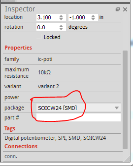
This isn’t an error (although there are a number in the AD5206 part in core). The chip is available in TSOP24 which is what the core part uses, and SOIPW24 (which looks to be what you have.) One solution is to change to the TSOP24 part and it should fit as is. Otherwise, as @opera_night suggested modifying the pads is a quick fix, but for me (probably not for you yet) it was pretty trivial to replace the pcb svg with a (fixed up, because the one in core is also broken) SOICW24 footprint, then change the fzp file to make it a new variant. That produces this:
If you load this in to fritzing you will find that the AD5206 now has a new SOICW24 variant in Inspector which has (probably) the footprint you need:
along with the original 2 (24 dip and 24tsop which it calls incorrectly SO28 instead of tsop24). To replace your current part in your sketch, right click the AD5206 and click delete minus. This deletes the part but leaves the routed traces. Now select the AD5206 in your mine parts bin (which will be the SOICW24 variant) and drag it in to schematic (because of a Fritzing bug I haven’t found yet, the schematic image is randomly rotated if you drag it in to any other view) and place the part over the existing traces. Switching to pcb will give you a wider part. Now you need to grab the end of every connection in every view and move it back and forth until the connectors go from red (not connected) to green (connected) to install the new part. This is a pain, but usually less of a pain the rerouting much of your sketch.
Almost certainly doing what I did, Clone the part and replace the pcb footprint with a correct one, or modify the existing footprint to do what you need. That is less work than recreating all three views.
I appear to have elected myself somebody (as in somebody should make a better parts tutorial). I kept notes and svgs when I fixed up the s4a edu module for someone a while back and am using that to make a new parts making tutorial. Should be out soon for some value of soon .
Ball is in my court there too. I’m working on an upgrade to the parts checking script that will be added to the parts submit tool chain and complain and reject the part (with suggestions how to fix it where possible) if the part does not meet standards. It too should be soon, for some extended value of soon (I find parts making much easier and less frustrating then development, and tend to stop and make parts when frustrated by development )
Once that is finished the big job starts: cleaning up the current parts in core so they pass the check (many do not pass the current lighter test script). That will be a substantial amount of work, since the parts all need to be obsoleted, and the obsoleting mechanism is, AFAIK undocumented (another thing on my list to do, it is a very long list .) So more people willing and able to help will be welcome.
I have made the mistake of electing myself “somebody” (as in “somebody should make a parts creation tutorial”) again. As punishment for this rash mistake, a single “here is how I fixed up this part” post has turned in to (so far ) 5 posts. These first three are infrastructure type posts that should be useful standalone. This one covers rescaling a drawing using Inkscape. It is being posted first because the real first document Configure Inkscape refers to this document and I needed the forum url to include. Such is life.
How to rescale a svg file to have the appropriate scale for Fritzing using Inkscape. First download this svg to work on. Note due to the fact the forum has trouble with svgs, this svg has been renamed to .fzp (which the forum uploads without trying to render.) So to get the svg download this file, then remove the trailing .fzp extension to leave you with the svg file.
After you download this, remove the trailing .fzp from the filename. The forums try and render svg files, and often fail with valid svg files. It will however load a .fzp file that is really a svg file without problem.
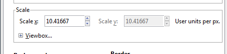
I started with the ‘svg.breadboard.S4A EDU_78c08539140e87873a7d0ebd198bd086_1_breadboard.svg’ file and loaded it in to Inkscape (which I used for this entire project, if someone would like to modify this post to use Illustrator, Coral Draw, Gravid, or one of the other svg editors that would be much apperciated!) as I use Inkscape to make Fritzing parts rather than one of the others. That indicated a problem, the scale is wrong, in Document Properties->Scale->Scale x:, the scale is 0.26458 rather than the desireable for Fritzing 10.41667 (which sets the view box to the desired 1/100 scale specified in the parts file format at
which you should read before and during making parts.
To correct that it is necessary to ungroup the entire svg so in Inkscape’s xml editor (Edit->XML Editor) select the g14 group and hit cntrl-shift-g (keyboard shortcut for ungroup) multiple times to ungroup. That finally produces path819 which if you do edit->select all will show as a 20in by 20in invisible rectangle which serves no purpose so delete it. Now do Edit->select all and then Document Properties->Custom size->Resize page to content->Resize page to drawing or selection. This is a very common sequence in Friting part making. It should be the last thing you do before re grouping the part, because it resets the view box and origin to the bottom left of the part and not doing it will sometimes cause scaling or offset problems in Fritzing. Now select group g1711 (the rest of the current part) and hit cntrl-shift-g multiple times again until there are no more groups in the image. Note for a large complex part this can take a lot of time and Inkscape will appear to hang while it does the calculations (removing the transforms from the document) be patient, it will usually eventually complete. You should end up with a document that looks like this:
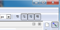
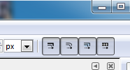
First insure that Edit->preferences->Behavior->Transforms->Scale stroke width is ticked (the easy way to do that is via the tool bar rather than the preferences menu):
Wrong (scale stroke-width disabled):
Right (scale stroke-width enabled):
Now we are going to rescale the document to the desired scale. To do so Edit->select all, then record the starting coordinates (with the tool bar set to px for maximum resolution) from the Inkscape tool bar here:
you will likely need to click Edit->select all to reselect the now invisible (due to small size) document. Now to complet the rescale we need to set the tool bar back to the original settings.
set x 0 y 0 w 161.905 h 315.603 in the tool bar. Note some times (the conditions for which I don’t know, but think involve rescaling elements with stroke and non zero stroke width) the x or y origins will change along with the w and h and you need to reapply the starting coords several times until the end result is the tool bar is set to x 0 y 0 w 161.905 h 315.603. That did not occur in this instance, the document resized correctly the first time. If anyone know why this is and how to avoid it I would really like to know. The end result should look like this:
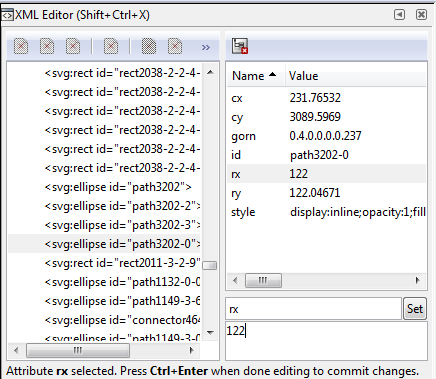
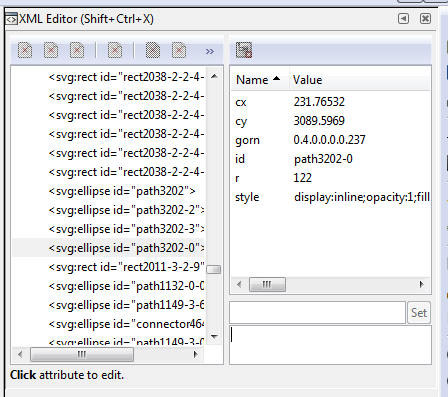
One unfortunate side effect of rescaling (due to floating point round off) is that circles in the original document will often become ellipses in the scaled document. As well as being wrong if the original element was a circle, in the pcb svg for connector pins, this becomes fatal as the gerber code will not create a hole in the pad if the pad is an ellipse. The only cure I know of for this is to manually change the radius of the element back to the original size via xml editor. A more efficient way (especially for a large number of elements) is to use global substituion in a text editor or write a python script (which I have not done yet) to do it automatically. In this case the original document has ellipses rather than circles so I converted one mounting hole before scaling from an ellipse to a circle:
So do the same thing again, change rx and ry via xml editor to the same value and it turns back in to a circle.
repeat for all the rest of the circles. For pads that have a square, or an oblong path (to make a non circular pad), they have an underlying circle to make the hole (that is the only way Fritzing will make the hole). The rescale may have altered the positions so you need to correct that if it has happened. To do that record the x y coords of the circle and its diameter from the tool bar. First change the w and h of the rectange or path to match those of the circle. Then change the x and y coords of the rectangle or path to be the same as the circle’s (we did w and h first, because changing them will change the x y coords too.) At this point you want to first fix up the view box in case the changes have modified it in a bad (to Fritzing) way. So do
Now do Edit->select all and then Document Properties->Custom size->Resize page to content->Resize page to drawing or selection to reset the viewbox, then File->Save as type plain svg to save the resulting document in a Fritzing friendly format.
You now have a properly rescaled document and can continue on with making your part. Why it is desirable to rescale the document is somewhat of a mystery, although here are my reasons: it is called for in the parts file format. Unfortunately I wasn’t involved in Fritzing when the developers that wrote the parts file format document were still involved, so I don’t know their reasons but I assume they had them. From my point of view a known scale makes automated checking of the spacing in documents by the part checking script easier. The script doesn’t yet do so, but in future I hope it will. The script does declare an error which when the script becomes part of the parts submit tool chain will stop the part from being accepted. From a selfish standpoint it makes it easier to figure out and/or change the size of a hole in pcb view. For Inkscape, the hole diameter in pcb is size = pad diameter + (2 * stroke width). With the scale set to 10.41667 and the standard 20 thou ring size, a .1 header hole (which should be 0.038in hole diameter) is stroke-width 20 * 2 = 40 + desired hole size 0.038, making the pad diameter 0.078in. So setting the w and h of the pad circle to 0.078in will give you the correct radius of the circle (it will also move the circle in x and/or y) so record the radius value from xml editor, then use Edit->undo to back off your w and h changes and instead change the r field in xml editor to the new radius you recorded from xml editor. This increases the radius of the circle (referenced to the center of the circle) and thus does not change the x / y position of the circle (or more correctly changes x and y evenly around the center) maintaining the 0.1in pitch between pads. Laziness at work.
Install Inkscape 0.92.4 (or more current version, 1.0 is in beta now but not stable enough to use)
Start Inkscape
select File->Document Properties
which gives this as the default starting point. I do not know how (or if it is possible) to configure this in the preferences file or other config file, so it will open with a different default. If someone does, please post.
unfortunately you need to do this for every document from the gui it appears. In the case of an existing svg file, the two unit changes should just work, but if the scale is not 10.41667 you will need to rescale the document in which case see
Now change the Inkscape preferences (this only needs to be done once, and will be written in to the preferences.xml file for later invocations)
Open Inkscape and click Edit->preferences
click on the + before Interface to expand the menu to get to Windows and Grids
Edit->preferences->Interface->Windows->Default window size from Maximized to Large
I prefer to open with a window that isn’t full screen, but large, pick which you like.
x and y offest of 0.005in so a 10 thousandth inch wide line in schematic will be centered on a grid line when it is on a 0.1in boundary. This makes visually checking alignment easy. You can change this from the File->Document Properties->grids page on the fly in a document if you need to align the grid to a pin that is off the .1in grid which is sometimes useful. Changing Major grid lines from every from 5 to 10 means (along with the 0.01in Spacings) that at high zooms you will see 10 minor grid lines between two 0.1in major grid lines. This makes aligning something exactly between two 0.1in lines easy. When you zoom out the minor lines disappear leaving you with only the 0.1 in major lines visible. Again change this to your preference. Having set this in preferences, just close the dialog window and it will write the changes out to the preferences.xml file the location of which can be found in
Edit->preferences->Input/Output->System as shown here:
I find it to be a useful practice to take a copy of this file in to preferences-install.xml, because I regularly do something (probably an accidental key press that sets some hot key) that screws up the operation of Inkscape. In such a case, close Inkscape, copy the saved preferences-install.xml file in to preferences.xml then restart Inkscape and you should be good to go again til the next time. You can also just delete the preferences.xml file and Inkscape when it starts will create a new one with default settings (you then need to make the above grid changes again though, and I am lazy …) The one other thing to note on Inkscape is that it is best for Fritzing to use File->Save as then in the “Save as type” field at the bottom select Plain SVG rather than the default Inscape SVG (which adds a bunch of Inkscape specific xml that Fritzing doesn’t always deal well with.)
Below is an example of what this gives you in relation to a Fritzing part. This is a simple two pin schematic svg zoomed out, so you see the 10 minor grid lines and how both the pin and the terminalId align to the grid when properly positioned on .1in boundaries. The scale (on the right) is set to 10.41667 as it should be and Units (a bit above that) is set to in. Setting the Units to px is an error, as px has had at least 3 definitions, 72dpi (early Adobe Illustrator), 90dpi (Inkscape 0.92.1 or .2 I think) and 96dpi (Inkscape 0.9.2.3 and later). Fritzing attempts to guess which dpi was in use, and often gets it wrong which results in scaling problems in your part. If you run across an old part that is dimensioned in px, you can (with difficulty!) use the rescaling howto to rescale the drawing appropriately and then save it with Units of either in or mm (which are not subject to guessing about what the dpi was.) Happy part making!
Of note here is the corner of the rectangle. Due to the 0.11in / 0.210in width and height and the fact that the stroke-width of the rectangle is 10 (10 thou in in the real world) the center of the rectangle lines are on the center of the grid. Similarly with the terminalId at height / width 10 (again 10 thou in in the real world) and at x at 0.300 in and y at 0.100in the center of the rectangle (where Fritzing will connect a wire) is at the center of the 10 thou wide line of the terminal so a wire will connect correctly to the terminal in Fritzing. This makes it easy to insure the pins are on 0.1in boundaries as they should be.
the same document except zoomed out til the minor lines disappear, leaving only the .1in grid
and finally the svg file itself so you can load it and play with it. Note you need to remove the trailing .fzp because the forum has trouble with svg files but will accept an svg file called a fzp file just fine (and it turns back in to an svg file when you remove the trailing .fzp).
A simple way to Scale in Inkscape is to:
• open the desired svg
• the fields at top of panel show Dimensions and Unit selection box. Change the Units from mm or inch to Percentage.
• Enter the desired value.
•• For Example:
If Width = 80mm and you want it to be 100mm (for Fritzing), enter 125% (which is 100/80 = 125%).
Naturally, you can do it for all the content of on selected items…
This is a Fritzing schematic template file for use when you want to make a schematic svg from scratch (which I usually do as I find it easiest). It is set to the proper scale as explained in this howto
This simple one has connectors with terminalIds and labels on all 4 sides of the rectangle with the text-anchor set to the value appropate for the position. The label has text id label which is special, no matter what you put in it in the svg, it will be replaced with the text from the title field of the fzp file by Fritzing when the svg is loaded. If you (as I often do) want to put text that will not be substituted, change the id label to text1234 (really anything except label) and the substitution will not be done.
This is the svg file itself so you can load it and play with it. Note you need to remove the trailing .fzp because the forum has trouble with svg files but will accept an svg file called a fzp file just fine (and it turns back in to an svg file when you remove the trailing .fzp.)
The advanced template below, adds the “group connectors” part of the graphics standard and details how I deal with dual row headers in schematic. This maps the linear nature of schematic to the physical (dual row) real world connector to make it obvious which pin is which on the physical connector. It also demonstrates how to do “group connectors” that meet the requirements of the parts file format document.
With that established a brief example of making a schematic from the simple template. The part I am going to make is a motor driver labeled Fake Part with direction and speed inputs and two output terminals for each motor. To start first load the simple template file in to Inkscape. Note due to the forum often having trouble rendering svg files, you need to down load the above .fzp file, then remove the trailing .fzg to get the svg file to load in Inkscape.) Next File->save As, change the file name from svg.schematic.simple-schematic template_1_schematic.svg to svg.schematic.test_1_schematic.svg so you don’t overwrite the template file on a save (if you do, you can just reload it though!) Now View->Page_grid to show the page grid (which hopefully is set by your preferences file to this) :
Now insure that ‘Edit->preferences->Behavior->Transforms->Scale stroke width’ is unticked, the easy way to do that is via the tool bar by clicking this icon till it is light (unticked). If you do not do this Inkscape will increase or decrease the stroke-width of an element when you increase or decrease its length or width. We do not want the stroke width to change, we want all (or at least most) lines to have a stroke-width of 10 to match the size of a wire in Fritzing at this scale.
then set the tool bar units to in (for inches). That (after zooming out a bit and selecting connector0terminal in the xml editor) should get you this:
Of note in this image is that the grid is set at .01in for minor lines and .1in for major lines (the darker blue). The border rectangle. pins and terminals (with some exceptions for the pins which are offset .05in on the top and right side of the rectangle) are on .1 in boundaries as sbown by the x/y coords at the top of the tool bar. This layout produces this:
Here we see that the 10 thou square that is connector0terminal exactly overlaps the rounded edge of the 10 thou stroke-width connector0pin. The result of this is that a wire connected to pin 1 of the part (connector0terminal) will mesh exactly at any angle with the pin of the part. A very common error is to forget to add connector0terminal in schematic, and thus the wire will connect in the center (i.e. 0.05 in to the right of the position of connector0terminal) making an ugly and incorrect connection for anything except a straight in connection. In addition with Inkscape set like this, if I put a selection box around connector0pin and connector0terminal, duplicate them and then click the up or down arrow on the x or y coord on the tool bar, the new pin will move exactly .1 in in x or y (depending on which button you click) creating a new connector (but without the correct ids) and positioning it correctly. It is possible and efficient to do entire groups (2, 4 however many you need) connectors the same way. For now I am going to assume this schematic needs to 2 pin inputs (which by convention will be on the left side of the rectangle) and two 2 pin output connections (by convention on the right side of the rectangle) and that I need some longer pin labels so I need to make the rectangle both higher and wider than it currently is. But first I need to delete the unwanted pins on the top and bottom of the rectangle. To do so draw a selection box around them and hit the delete key.
Note that I selected all of the connector line, the connector terminal and all the labels, I then did the same to the two terminals on the bottom of the rectangle and deleted them as well which results in this:
Now I am ready to duplicate pins 1 and 2 to make and place a second 2 pin connector on the left of the rectangle. So drag a select box around the pin terminal and labels for the two pins like this:
then right click and select duplicate to do the duplication. Nothing in the canvess appears to change because currently the duplicate are on top of the original elements. However in the xml editor window on the right we see a bunch of new elements (the same as those we selected but with new ids) have appeared as a result of the duplication. The elements outlined in blue (the text elements are probably not correct, but the number of elements is) have been duplicated and re id ed in to the section in red creating our two new pins on top of the existing ones and (conveniently) selecting them.
the selected two connectors move down in y by 0.3in leaving a 0.1in separation between the two connectors leaving the original connectors in their original position. In general it is desirable to make schematic as small as possible so as many parts as possible will fit in a single drawing. As well you will note that this movement has moved the new 1 B connector outside the viewbox, which would cause it to be truncated by Fritzing if loaded like this. We will fix the view box later though. Now I am going to do the same thing (without the images) to the F and E connectors on the other side of the rectangle. Now I will select the rectangle and move it down 0.3in in y the same way, leaving its new staring point at -0.200in. Now switch to the H increment bar and click it 3 times to increase the height of the rectangle to 0.61in restoring the rectangle to being 0.1in below the bottom connector and 0.1in above the top connector as is desirable. I have arbitrarily decided I am making a two channel motor driver module, with inputs for speed and direction and outputs for the motor terminals. As we see there is not enough room for the necessary pin labels (and label is in the wrong place but we will fix that later). Becasue the viewbox line through the middle of the part is annoying me, at this point I’m going to do an Edit->select all, then click Document Properties->Resize Page to content…->Resize page to drawing or selection to reset the viewbox to surround the part (I will do this multiple times as the document changes to keep it readable). That produces this:
Now I need to move the connectors on the right side of the rectange further to the right to make room to add the text for the two motor connections on the right and then resize the width of the rectangle to match the new connector positions.
Note I started above the select box rectangle back at the trailing characters of the label and left side connector labels. Because the entire element of the label text and the rectangle are not in the select box it only selects the connectors that I want to move. That produces this:
I intentionally captured this while only part way through entering the B Motor 2 text to illustrate the use of text-anchor start, end and middle. In this case the text-anchor is set to end:
That means the text is anchored to the end of the characters and as I type in new values in the xml editor it will expand the text to the left, leaving the last character in the correct position from the pin and the rectangle (when I move it there.) The label is set to text-anchor:middle and thus will expand to both left and right leaving the center of the text in the approptiate position, and the labels on the left are set to text-anchor:start so they will expand the charaters to the right leaving the start character the correct distance from the pin (as long as its initial position is correct which it is in this case.) All of this is in aid of lazyness, doing this I don’t have to (at least usually) reposition the text after making a change. lazy is good as far as I am concerned. So I finished the text, and changed label from label to Fake Part, but in this case that doesn’t matter. Because the text id on the Fake Part text is set to ‘label’, Fritzing will substitute the text from the Title field in the fzp file in place of this text and the final part will have whatever test is in Title in place of Fake Part. If you want Fake Part to appear no matter, change the id field from label to label1 (really anything other than label) and the substitution will not take place. Now the part is cosmetically complete. The only thing left to do is to correct the pin definitions (remember the connector0pin and connector1terminal fields were changed to line123 and rect123 when we duplicated them) so we need to use xml editor to assign the pin numbers that are specified in the fzp file to the appropriate pins (this can also be done in Parts Editor although I am rarely successful doing it and thus avoid Parts Editor.) In this case I will assign the connector numbers as one less than the pin number i.e. Pin 1 in the drawing is connector0pin, pin 2 is connector1pin. Confusing, but how Fritzing wants the pins labeled. Pins 1 and 2 (connector0 and 1) are correct from the initial part so we start with pin 3 (connector2) and use xml editor to set the id field on the line to connector2pin and the rectangle below it to connector2terminal which looks like this currently:
At this point, schematic could be considered finished as it will work without problem as is. I prefer to do one last optional step to make later maintenance easier: Arrange the pins in order at the bottom of the xml edit window so they are easy to find by doing this:
With the pin (and then the terminal for that pin) selected press the tool bar button outlines in red. That moves the pin to the bottom of the xml window. Repeat with the other pins to end up with this:
Now we are ready to resize, regroup and save the finished svg. So Edit->Select All, then click Document Properties->Resize Page to content…->Resize page to drawing or selection to reset the viewbox to surround the part. With the edit select all still active use either cntrl-g from the keyboard or Object->Group from the tool bar to create a group from the entire image like this:
Thanks for sharing, the sponsored download version on the site includes the parts but on Ubuntu the screen aspect ratio for this version seems set at ±120% so the parts are out of screen. Your workaround for installing the parts worked and apt version seems to set the correct screen aspect ratio.

 ). The next problem is schematic. There are 4 physical pins spaced like this: