Do you have a question? If so I’m not clear on what the question is.
Peter
Do you have a question? If so I’m not clear on what the question is.
Peter
Since I see the forum doesn’t seem to have noticed the edit, there is an error in the posted part which I have corrected and posted a new version replacing the old one. If you have downloaded this part, please download it again to get the corrected part.
Peter
Coolness! I’ll take a look at that tomorrow. (The ability to unplug would be good, but it’s not a deal-breaker.)
And like I implied earlier (or at least tried to), I’m not doing much with it right away. I actually just had the problem in front of me and wasn’t going to rest well until I had a good idea of what mistakes I was making.
What you wanna ask? I just dont understand
Ohh wow, I also have this, I bought it from Black Friday coupons at Reecoupons, for my son, because it enhance its knowledge and way of his thinking, I suggest every parents must buy this for their kids, it will help them to learn. Its much expensive in local shops but luckily I found it on reecoupons.
fritzing can provide 128 mil highest in pcb trace. And my local market provides 1oz copper pcb board. I need 30 amps to pass. For 1oz copper pcb how much trace should be used for my 30 amp connection??
As always google is your friend (and the first place to start when looking for Fritzing parts). A search for “fritzing part ACS712” turns up a variety of options. I’d use this one (his parts are generally decent):
http://omnigatherum.ca/wp/?p=338
the web page is a bit weird, you need to right click on the text and select “save link as” to download the .fzpz file for the part (file->open in fritzing will load it.)
Peter
Actually Fritzing will provide a maximum 255 mil trace if you type 255 in to the trace width field. The 128 mil width is only the p;ull down limitation. There is a bug in the gerber code that may make placing this exciting though (any largish trace, not just 255 mil.) the fix has not been commited yet, possibly due to a merge conflict that no one has so far had time to figure out.
Again google might be your friend. A search for “pcb trace width 1oz copper 30A” turns up
http://circuitcalculator.com/wordpress/2006/01/31/pcb-trace-width-calculator/
which claims to calculate trace widths given a variety of inputs. Never used this but it looks reasonable. You may well be better to look at one of the fabs that can do 2oz or more (if they do more) copper though for this kind of current as 2 oz copper halves the required trace width roughly which is a big win on board space. Also keep your high current traces as short as you can (i.e get it off the pcb in to wire as soon as you can.) Good luck!
Peter
Yeah, it looks like something like this would be just the ticket, in actual practice. The good news is that, unless there’s something there that I’m missing, I wouldn’t even (necessarily) have to change the board’s design, for general use; it should fit fine as is. Great find, Peter! Thank you!
You may need to adjust the hole size down a bit, the pins on these are IC size (which Fritzing uses a 0.035in hole for rather than 0.038in. As I recall (I don’t have one to hand) there is a larger lip at the top of the pin I think meant to press fit them in to a plated through hole. In your case where height matters you probably want the hole big enough to allow that lip to fit in it to minimize the height. I also had problems finding any on ebay, there used to be some listings with 10 each male and female 140 strips for I think about $5 (I bought some 5 or 10 years ago) but I can’t find such a listing now (which may just be wrong search terms.) when a single strip of 150 was $6 from digikey (to be fair, I think the digi ones were gold and the ebay tin, but still …)
Peter
The Harwin pins I found (link above) don’t appear to have that issue, and $3.80 for a strip of 30 (since 16-18 would be needed for this project) doesn’t seem too bad. Plus, I can keep researching other brands for a lower price and better fit.
It isn’t quite as big as the ones I have but it is there. From the digi listing, the mechanical drawing shows the lip:
it looks to be only .5mm, and the one dimension missing is the diameter of that lip but calipers on the part will give you that, but with a hole the lip fits into you save .5mm in height on the top and .85mm on the bottom (you may only get one or the other because the LCD hole won’t be changeable, so I’d go for the 0.85mm saving on your board.) I think the ones I have are similar about a 1mm lip on the top of the pin, not much but also easy to recover with a simple hole size change on your board.
Peter
At present email notifications of new posts or replies is broken. I think the web site may be sending them (although I’m also not sure that is true either  .) The web site is old and pretty broken (little maintenance for the last 4 years), but due to suspected spam bots (again suspected but not confirmed last I heard) the site is on many spam block lists and the mail gets classified as spam or discarded. The bottom line is that you will not (at present at least) get an email notification that someone has replied to your post as you used to. So you need to check for new posts after you post something. Hopefully this will get fixed (the folks are working on a new web site I believe) but for now this appears to be how it is.
Peter
How much of a problem would it actually be to leave the holes at 0.043"? Would 0.008" really be that significant? (I haven’t soldered anything in many, many moons.)
Solder isn’t all the strong, you usually want a fairly tight fitting hole to provide mechanical strength, and in this case you are going to have movement as well which will make things worse, so I expect it is desirable to have the holes as close to the pins as practical, bending the pins of the connector over so they lay against the pad and hold the connector in mechanically would help some. The usual recommendation is have a strong mechanical join before soldering. All that said, I don’t have any experience with wearables, so you may be best to ask in the adafruit forurms or a wearable forum somewhere what people who have done its experience and recommendation is.
Peter
Well, that’s part of what the mounting holes are for. I’m working up some spacers even at this moment. 
(post withdrawn by author, will be automatically deleted in 24 hours unless flagged)
Thanks peter. I searched in google. I found this link but i could not get any access from my country . Don’t know why !!! So now i am going to use vpn . Generally I don’t use 'em.
I used that calculator before this forum stuffs. But always shows me some weird values. That’s why I posted it in forum.
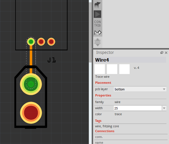
can’t type 255. It remains 25 (trace is just for example not specific for any device.)
And Thanks a lot for helping me out

