AsusN552.fz (191.9 KB)
Hello, is there anyone who can translate this file into a working Fritzing file (.fzz), or extract a net- and part list, for altium designer or any other major electronic design file.
↧
.fz file reads in Fritzing with an error "fritzing analyse fout (1) op lijn 1, kolom 1: error occurred while parsing element"
↧
.fz file reads in Fritzing with an error "fritzing analyse fout (1) op lijn 1, kolom 1: error occurred while parsing element"
Probably not as this doesn’t appear to be a .fz file (which is xml), nor does it appear to be a valid zip file.
AsusN552.fz
gâÇ–Û"¸/’jXÆáÙ‚uê*[árŒE³Ç©¼„#!©AòŠò
O¢þà ‰ïKL•»{°
ââ=H
…
a proper .fz file looks like this:
not-routed.fz
<?xml version="1.0" encoding="UTF-8"?><module fritzingVersion="0.9.4.2019-12-01.CD-498-0-a1ffcea">
<boards>
<board moduleId="TwoLayerRectanglePCBModuleID" title="Rectangular PCB - Resizable" instance="PCB1" width="8.46667cm" height="5.64444cm"/>
</boards>
…
unless there is an odd utf encoding on the original file that I’m missing.
Peter
↧
↧
Mega2560 R3 Pro Mini
Not a big problem, it is only a minor change to convert the pro mini in to this one (delete 6 pins, add the usb connector back in, add 2 power pins) to make one of these from the pro mini board (and we have a pro mini if someone else wants one.) Once you are used to making parts changing them is fairly easy.
Mega-pro-ch340g-ATmega2560.fzpz (30.8 KB)
Peter
↧
Howto create Custom part (pot)
Hi Peter, good morning,
wouw, I did not expect to find this part by google search … great.
I do not need the 90° version, but the pinning and the PCB-position is the same, so it will work.
Thanks so much for help.
Cappy
↧
Producing PCB's from .dxf files
Hi Gents and Ladies
I’m a newbie to Fritzing, and I’m hoping to eventually use it to help me produce some PCB’s that at the moment I am struggling to make.
Some backgound, I am one of those home bodgers who is always making some crackpot project and as a result is always learning. The current project is a homemade flight simulator rig to work with the DCS A10-C program. There is a whole forum dedicated to it that has loads of information and help with the individual panels, plus a clever guy came up with a program called DCS BIOS which outputs the game info to switches, LED’s, LCD displays and stepper motors for gauges using Arduino Nano boards.
It’s a fantastic job that they have done, and as a result I now have really professional looking ‘cockpit’ panels that interact with the game. Along the way I have learned how to use a 3D printer, CNC engraver, Co2 laser cutter and of course the programs that design the parts and convert them into files that can be used to drive the machines mentioned above, namely Solidworks, Qcad, Inkscape, CamBam, Universal Gcode sender and K40 Whisperer.
All in all I’m quite proud of what this old brain has managed to learn and produce.
As part of all this I am having to produce a load of PCB’s. Most are one-offs, as each is designed for a very specific job, and fit in very specific places and spaces. As they (generally) are not very sophisticated, I have been using a combination of Solidworks for designing them, then convert to .dxf files and so onto the the CNC engraver via CamBam where I am able to engrave blank PCB sheet with the circuit lines (don’t know what the proper word is) plus the solder pads for the switches, LED’s, rotary encoders and headers, and the CNC machine makes short work of drilling the holes and cutouts and the often irregular external profile.
For small, low density single sided PCB’s this is fine. I can even make double sided PCB’s again with the caveat that they are small and low density.
However the big issue is that the PCB board is very often warped, which when it comes to larger boards means that the circuitry cannot be cut evenly across the board, despite leveling software. As a result the circuits can end up breaking through or pulling up, so I have to use a minimum of 1.5 mm for any contact lines in order to have a chance of them not getting ruined, and of course ruining the boards. Plenty have ended up that way.
Additionally when I need higher density of ‘lines’ due to constrictions in the board or the need to avoid components, it means that often the copper ends up being machined through at some point due to the uneven surface.
I tried the method I found on the internet of using paint and the laser engraver to expose the copper for etching, with 100% failure rate. Even if it did work, the warpage that it gives the boards would make them unusable.
The irony is that with the .dxf file I can make absolutely ideal PCB’s, even double sided ones, I just can’t convert them into reality.
I have looked at various forum posts that use inkscape to make SVG files, and have struggled with it despite using inkscape quite a lot. The idea that I can take the .dxf file with the exact position of the solder pads and terminals, plus the outside profile of the board with all the necessary cut outs, mounting holes and contact holes all exactly placed, and then import that into Fritzing where I can then put in the contact lines and through holes (vias, i believe?) so that I can get one of those PCB manufacturers to make it for me really appeals.
So that is what I need, a workflow that takes me from a dxf file to a Fritzing PCB output file.
If any of you kind people can advise or direct me to somewhere that shows how to do this is a logical manner, preferably with explanations so I can understand the concept rather than just repeat parrot fashion, I would be eternally grateful!
If you need me to show example files or anything, let me know
Cheers
Les
↧
↧
How to add osoyoo LoRa Module
I searching how to add the same module for lora in my project as the link below
https://osoyoo.com/wp-content/uploads/2018/07/lora-transmissor-777.png
and thank you so much for advanced
↧
Fix Epson Workforce WF-3640 Blurry Printing
I am a doctor. In my hospital, I am using an Epson printer to print reposts. But days ago I saw the printer take 15minits to print a single page. I want to know how to Fix Epson Workforce WF-3640 Blurry Printing machine immediately.
↧
Howto create Custom part (pot)
Hi again,
I checked the item again …
Unfortunately it is not exactely what I am looking for.
I need the W-variant: BOURNS 3266W
That means the middle pin inot in a row with pin 1 and 3 …
I am still searching … but no result so far.
Cappy
↧
Howto create Custom part (pot)
A new part was needed (fairly trivial for me to do, probably less so for you  .) While I was there I reduced the size of the hole from 0.04in to 0.03in (because the pin is 0.018in according to the data sheet) and moved the middle pin down by .1 in:
Trimpot-#3266w.fzpz (5.9 KB)
Peter
↧
↧
Fix Epson Workforce WF-3640 Blurry Printing
You would need to find a Epson printer forum, this forum is about Fritzing (a printed circuit board package) not printers.
Peter
↧
Producing PCB's from .dxf files
I’m not aware of a conversion program from dxf files to Fritzing. There is one for eagle files to Fritzing, if Eagle will import dxf files though (I don’t use Eagle enough to know if that is possible, if no one here answers, possibly ask in the Eagle forums?) A quick google search indicates that Eagle will import dxf files so if you upload an example dxf file you need (you will probably have to append a .fzp to the end of it as I doubt the forum will allow the upload of a dxf, file although I could be wrong), I’ll try and run it through Eagle2Fritzing (which is non trivial to install) and see what comes out. That would probably be your best bet for an automated solution. A manual conversion is likely to be a fair amount of work. If the dxf files are the entire board this probably won’t work as Eagle2Fritzing expects parts not entire boards, but we can try it and see.
Peter
↧
How to add osoyoo LoRa Module
It looks like they have but have not published a Fritzing part for this module. So you should ask them for the Fritzing part, or try one of the other ones that show up in a search for
fritzing part osoyoo lora module
which turns up several parts (although not for this particular unit) or we could make a new part if there is sufficient information available (which it looks like there is.) First try the osoyoo folks (because the other 2 modules found in the search are not suitable) and if they don’t respond ask here again and I’ll consider making one.
Peter
↧
Producing PCB's from .dxf files
You can succeed using .DXF and Inkscape. But, there are better approaches to consider.
As a ’Partial’ example of DXF/Inkscape success, below is screenshot of Opening a DXF in Inkscape and using the Gcode Extension to create the Gcode for machining.
It’s been a few years - old memory suggests you’ll need to dig into it but, it was fairly easy after headaches of learning the tricks (mostly with Inkscape).
Better Option(s):
Option 1) I do it this way.
Create the PCB design in Fritzing, Export Gerber files and load into CopperCam. Export the Gcode for machining. Simple. See comments below…
Option 2) Using a DXF, import into FreeCad, Export the Gcode. I have done this many times (mostly for non-PCB work) but don’t recommend it as it requires learning FreeCad.
Pretty easy for a SolidWorks user (the Part Design Workbench is similar enough to SolidWorks to make it Very doable in a couple of hours. I no longer use SolidWorks or ProE as FreeCad has matured to Professional usage.
It will be confusing, especially learning/working between the various Workbenches (Part_Design, Draft, Part, Path. Think of them as Individual Programs under one Umbrella called FreeCad).
Option 3) Using Eagle and plugin, you can do it all but, steeper learning curve.
Option 4) KiCad is like Eagle - but, has it’s own Stand-Alone programs (PCB, Schematic… etc) under the one umbrella called KiCad. I’m not sure about KiCad and Gcode, though in the past few months I’ve gotten quite familiar with KiCad. I use it to create the Gerbers and CopperCam for the Gcode.
The UpShot…
The most efficient and 100% success rate (without steep learning curve) will come from using Fritzing and CopperCam (or other Gcode from Gerber making program).
CopperCam has a Free download good for small projects. Link
Regarding Bowing/Non-Flat PCB’s:
I used 3M double-sided Tape. That worked well but eventually machined some holding frames… screenshot below…


↧
↧
Creating ESP32 SIM800 part
He he. Ok. I really think that Frizing is a good initiative and I think it would be smart to bring the donate button on to the Main page or at least somewhere in the forum. I will go ahead and donate.
I have easily created my first PCB and I have sent the order to AISLER.
Thanks for all your help Peter !!
↧
Part-creation-howto-part5-3d-images-howto
This is a continuation of
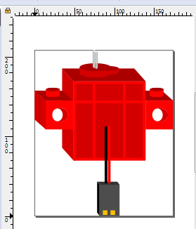
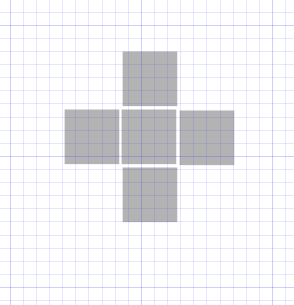
This demonstrates (with a completely new part) how to convert a minimal 2-D image part (a Yahboom lego motor in this case) in to a simulated 3-D part in breadboard via Inkscape. We will start from this part which is a basic 2-d representation of the part using nothing more than rectangles that looks like this:

svg.breadboard.yahboom-red-motor_1_breadboard-starting-2d.svg.fzp (4.3 KB)
(you need to remove the trailing .fzp from this to get the .svg file which this actually is due to forum limitations)
to this finished part. I will only cover breadboard here, schematic and pcb are ordinary, and can be created by following parts 1 to 4 in this series.
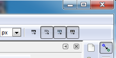
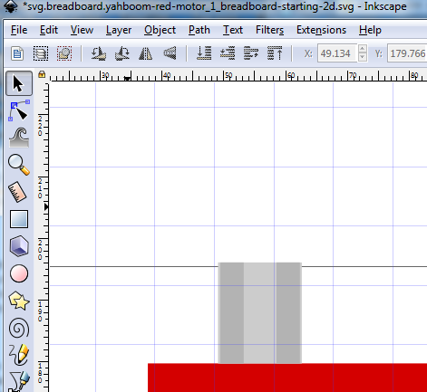
Start by copying svg.breadboard.yahboom-red-motor_1_breadboard-starting-2d.svg in to svg.breadboard.yahboom-red-motor_1_breadboard.svg then edit svg.breadboard.yahboom-red-motor_1_breadboard.svg in Inkscape and duplicate the base rectangle and move it left in x to clear the part. This is the starting template that we are going to skew, scale and recolor to make the 3-d image. First, though make sure scale stroke width is disabled (we don’t want that changing the dimensions as we try and align things!):
Then shut off snap to grid:
because we want to be able to scale exactly, not necessarily to the grid in this case.
Then duplicate and move the the left the base rectangle like this:

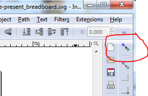
We want to end up with the skewed image to the right of the rectangle (to make the side of the body), to do that we first need to scale the initial rectangle narrower in x. We can do that either by reducing the width in the tool bar, or as in this case by clicking on the rectangle and click and drag the scale arrow (circled in blue here) towards the right til the rectangle is the right size (just take a guess at the size, you will need to iterate these moves until the skewed rectangle is the correct shape which is why to use the scale and skew arrows rather than the toolbar.)

Now click on the duplicated rectangle. The scale arrows will change to skew arrows like this:

click and drag the skew arrow circled in red towards the top of the screen. The rectangle will skew til it looks like the image. Now click and drag the skewed rectangle you just created til its bottom edge is aligned exactly with the bottom edge of the base rectangle like this:

At this point you can see the 3-d image starting to appear. The rest of this is pretty much repeating these steps (with lots of trial and error to get it looking right!) The other thing we are going to do but haven’t yet, is to change the color slightly to make panels that should go back darker in the same color (to go back) or lighter (to come forward.) Here is an example from the motor shaft in the original svg. Note the center rectangle in the shaft that is a lighter silver color to indicate the spline of the shaft:
but that is for later. For now we need to align and scale the skewed rectangle, so click and drag the skewed rectangle til there is a bit of white showing between it and the base rectangle like this, then select the the base rectangle, copy its y coord from the tool bar and use that to set the y coor of the skewed rectangle so they both start at the same y position like this:

where the rectangle (not selected here) is also y 69.141. Note that although we started from an identical sized rectangle the skew has made the leading edge shorter (outlined in blue) so we need to increase the height either with the tool bar or by dragging the y scale arrow on the top. But before doing that, we want to set the height/width lock, because if we do not, increasing the height will also increase the skew (as the width remains constant), with the lock set the width will scale to keep the skew constant as we increase the height which is what we want, the default is unlocked, because normally that is what we want.

so change that to locked for now.

Now we want to raise the top edge til it just meets the top edge of the base rectangle like this (the width will get slightly larger as well to keep the skew the same.) As noted you can either click and drag the top select bar to move the top edge higher, or (as I did) manually change the height value in the tool bar to bring the top edge of the skewed rectangle to meet the top of the rectangle like this:

If your svg looks like this instead of the above:

You need to select the skewed rectangle and move it to the top of xml editor by clicking the tool bar button circled in red. Now we are going to repeat what we just did with the tab on the side of the skewed rectangle. So duplicate the tab rectangle and move it to below the skewed rectangle, then change its color to match the skewed rectangle, and leaving the height identical to the tab, change the width and skew to match the skewed rectangle like this (w and h are still locked here):

Then move it in to position as you did with the skewed rectangle to produce this:

Now duplicate the front of the tab yet again, move it up a bit, set its color a shade or two darker then skew it to match the skew of the just created side piece like this:

Now you have to iterate the height / width / skew of the new piece until if fits exactly in to the space like this:

Of note here is the pin on the top is still present (I have selected it here) but is obsucured by the top. Since we are going to replace this with a circular column, just delete it at this point. To start making the pin on the top, create an ellipse with the circle tool:

then duplicate it, and make a rectangle as well. Now from the tool bar, set the x coord, width and height of all three (the two ellipses and the rectangle) to be identical. In my case the color was already the red of the top of the tab, if yours is not, set it to that. Set the color of the rectangle and bottom ellipse on shade lighter in red (so they won’t fade in to the tab when moved there later.) It should look like this:

Now move the rectangle down in y til its bottom edge is at the center of the bottom ellipse. Move the top ellipse down in y til its center is at the top of the rectangle like this:

Here we see we have a half peg (because of the order I created the ellipses.) Since I want a full peg I need to move the top ellipse up a couple of times until it is below the rectangle and thus fully visible (click the icon on the tool bar until the full top ellipse appears.) It should then look like this:

Now select the entire pin and move it in x and y to its final position on the top of the tab. (this motor is intended to be used with Lego blocks to build robots, thus the pin on a tab) like this:

Now let laziness rule and duplicate the entire construct and move it in x til it is on the opposite edge (which wants to be identical.) Note that the dark top is too high in the hierarchy and wants to move down:

Note that the dark top is too high in the hierarchy and wants to move down (by clicking the circled tool bar icon til the base is hidden like this):

Now will move on to making the motor shaft. I struggled with this, and tried a few unsuccessful things before going back to basics. The shaft is 5 squares like this which is the secret to making it (here split apart to show the 5 squares):
Then in document properties->grids set x and y offset from 0.05in to 0. In the tool bar set units to in then set the width and height of each square to 0.06in (as that is the width of each square) then move the center square to x 0.770in y 2.570in to be centered on x and y major grid lines (note actually doing this leaves a white line at the join between the left and center squares, to correct that I had to change dimensions to px and set left square x to 68.200px and center square x to 73.900px which translates to x 0.770in y 2.570in but without the white line between the squares due to floating point round off. Sometimes you have to get more precise than bare inches will give you to get what you need. Here 0.710in runs from 68.111px to 68.207px, so a value of 68.16 is good (right in the middle of the range). 68.111 comes up as 0.711in. So for extreme accuracy, use dimensions in px (for Inkscape 0.9.2.4 in use here,there are 96px per inch) In this case I used the drag arrows exactly on the grid lines to position the squares so there are no white lines between squares like this:

That gives me the top of the shaft. Now I need to add the lines down for the shaft splines. So duplicate the bottome square and move it down in y like this:

Then select the entire top of the shaft, set lock on w and height then skew the top of the shaft like this:

Now we can use the still straight square to make (and color) the shaft like this: drag the bottom scale bar to increase the size of the rectangle and change its color one size lighter:

Now duplicate the rectangle and then make it two steps darker (the top bar is one step darker!) to stand out from the top. Skew it to match the side of the skewed arm by scaling it inwards til they are the same size, iterate between scale and skew til it is correct like this:

Now the laziness principle takes hold and we duplicate the square column and move it to the places that need a square column, and duplicate the skewed column and copy it to where we need skewed columns which looks like this (which currently looks more like modern art than the shaft!):

To correct that we need to select the various new pieces and move them lower til the parts that should cover them do so and when needed change the color a shade lighter or darker to differentiate between two columns, leaving us with the final shaft:

Now we need to deal with the oddly shaped motor shaft bump on the top. First delete the two-d versions as unneeded (the grey piece is the shaft above it and the red square wants to be an ellipse):


duplicate the left side tab top and use it to make the top of the motor:


Now let laziness rule again and duplicate the pin on the left side (either one will do) for the top like this:

Then (with width height locked) stretch it out a bit with the scale arrow til it looks like this to make the top support for the shaft:

then duplicate it to make the side lobe of the housing, move it in x and then reduce the size of the top rectangle by a bit so we can make the top ellipse smaller without changing the size of the vertical part like this:

then reduce the size, move it to be on the end of the large ellipse and use the lower icon to make the shaft mounting tab look like this:

At this time I discovered that the shaft is too large to look right, and so need to go back and adjust that. I started with the front pillar (deleting the other 3 pillars as they will be recreated from the front one) and adjusted it til it looked square (as it is in real life) then duplicated the top panel to make the center square like this (with the center square slightly high in y so you can see it):

Now as the first time, duplicate and move and raise/lower the existing panels to form the new shaft:

Now we are going to create the illusion that the holes in the tabs are in fact a tube through the tab. To do so make the following (the grey rectangle is only so you can see the white ellipse.) The center rectangle is the back of the case and the right circle is the hole through the tab with fill set to a shade of red (darker than the tab). The left ellipse needs to be adjusted to work correctly when added to the mix.

now move the dark red circle to be centered in the tab:

Now move the ellipse over the circle to block part of it out to leave the impression of a tunnel like this:

(you may need to scale the ellipse to get the correct effect)
now move the rectangle over the red circle to create the rear wall of the back of the motor like this:

then do a similar thing on the other side (it won’t be identical to the left this time) to end up with this:
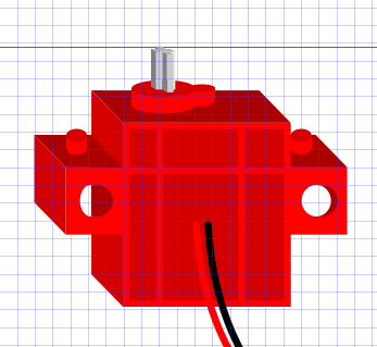
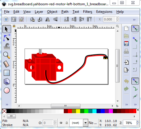
Now comes the connector. Up until now the connector was (as it is in real life) a .1 header. The problem is that the board it needs to connect to has two motor connectors .3in apart on the board. Because you can’t flip vertical in breadboard, that will mean four parts, a top/bottom left motor and a top/bottom right motor (the only difference being the position of the connector) but that is life. As part of this I replaced the two rectangles which were the wire with lines with line-cap:round, then did Path->Object to path to convert them to paths and used the path editing tool (there are Inkscape tutorials on using the path editing tool and I am not very good at it, and so will let you learn from the experts) to adjust the paths to look like the curved and flexible connecting wires. I as noted I reduced the size of the header to fit within .2 in (so two will fit within a .3in space.) This is the bottom left varient. There are 4 parts to this family, bottom left (this one) top left (the only change being the connector moves down til it would connect to a connector .3 in from the connector in the bottom left varient) and top and botton right which do the same thing on the other side with the connector flipping sides. The objective is to be able to connect the motors to their designed interface board (which supports 4 motors.) See also the family howto, to see how the variant field can be used to select these in Inspector in Fritzing here:
and finally the 4 motor variants as they would be deployed:

Note: as I write this, there is a bug in Fritzing which, even though the motors are connected (because the connections create rats nest lines in schematic) the routing (circled in red at the bottom) shows as incomplete. You need to connect the pins with wires in order to get the routing complete message at present even though this will work as is.
That completes this part’s breadboard. The schematic and pcb are standard, and the earlier howtos detail how to make them, so I won’t repeat that here (you can see them both in the final part here, it will be in the temp parts bin with the .fzz file loaded in to Fritzing):
not-routed.fzz (79.4 KB)
This series continues on to an explaination of the family and variant properties in:
↧
Part-creation-howto-part6-family-and-variant-howto
This is a continuation of
This demonstrates the intended use of the family and variant properties in the fzp file. The purpose of the family and variant fields are to allow the user via the variant field in Inspector (or sometimes fritzing for its self I think) to swap parts. For that to work all the parts in a family need to have the same number of connectors which connect to the same pin on the part (although as we see here, their position may be different between variants.) In this example I have a Yahboom super:bit interface board and 4 DC motor variants that connect to the super:bit board. The intended use looks like this:
here all 4 motors are connected to their appropriate connector on the super:bit. This is the .fzz file that the following images refer to so you can load this .fzz in to Fritzing and try the changes below for yourself and see the effect of changing the variant values. There are 4 motor parts here (they and the super-bit part will be in the temp parts bin when the not-routed.fzz file below is loaded in to Fritzing):
not-routed.fzz (79.4 KB)
which will have in the temp parts bin:
yahboom-red-motor-left-top.fzpz
yahboom-red-motor-left-bottom.fzpz
yahboom-red-motor-right-top.fzpz
yahboom-red-motor-right-bottom.fzpz
in all 4 cases the family property is
<property name="family">yahboom red dc motor</property>
but each part has a different variant property (according to motor name / position):
<property name="variant">variant left-top</property>

<property name="variant">variant left-bottom</property>

<property name="variant">variant right-top</property>

<property name="variant">variant right-bottom</property>
(note: the “variant” that starts each property is required, if it is omitted the variant will display in inspector but you can’t select the other values in the pull down menu because the menu is not instantiated.) If one of the variants has more or less connectors defined, you will get the “red square because a defined connection is missing” indication in the various views so you need to be careful that all the parts in a family really are interchangeable. There currently is no testing to insure this, but I intend to add such a check to the parts checking script. So that said lets try changing motor 1 from its correct variant of “variant left top” as shown here:

to each of the other variants in turn, this is left bottom:

Note because there were wires connection this motor to the super:bit they have been stretched to connect to the new position of the connector. If I now change motor 2 (which does not have wires connecting it to the super:bit), it should disconnect, as it is no longer connecting, but in fact does not (which is likely a bug!), instead the rats nest line in schematic remains and clicking on the motor connector lights the pin on the super-bit yellow indicating a connection (and the routed connections number has not changed.) Changing motor 2 back to bottom left and motor1 to “variant right top” again stretches the wires to the new connector position:

and similarly changing motor 1 to right bottom produces this effect:

This concludes the family / variant howto. Next is the suppressing pcb layer howto available here:
↧
Part-creation-howto-part7-suppress-pcb-layer-howto
this is a continuation of the family and variant howto here:
This howto details the various ways to suppress the pcb layer in a part. As with the earlier parts of this series I will use the yahboom super-bit part as the example. Because there is a 18650 battery (and a BBC micro:bit plugged in vertically to a socket on the super:bit) it isn’t practical to place a pcb on top of the super:bit. Rather than do the work (there are 86 connectors!) required to make pcb view work, I chose to suppress pcb view instead. The official way to suppress pcb view (as explained in the parts files format document available here:
is to use the Hybrid Connectors property (described in a section called Hybrid connectors (optional) near the bottom of the document. Below is an example of where this is useful using a barrel adapter part that has screw terminals (the other common case to want to suppress pcb view):

here we have a 2.1 barrel adapter to screw terminal adapter. Actually neither of these translate well to pcb, but the screw terminal part is an example that often wants to be suppressed in pcb, so that is what we will do here. There are at least two ways to do that, by setting hybrid=“yes” in the fzp file (which in this case runs in to a Fritzing bug) and eliminating the pcbview section of the screw terminal connectors in the fzp file (which is what I actually did in the published part.) Lets start with the variant 2 part which uses hybrid=“yes”. This is in this Fritzing part:
2.1mm Barrel Jack with Terminal Block-improved-hybrid.fzpz (6.4 KB)
and the relevant section of the fzp file looks like this:
<connectors>
  <connector id="connector0" type="male" name="POS-TERM">
    <description>positive connector terminal block</description>
    <views>
      <breadboardView>
        <p layer="breadboard" svgId="connector0pin"/>
      </breadboardView>
      <schematicView>
        <p layer="schematic" svgId="connector0pin" terminalId="connector0terminal"/>
      </schematicView>
      <pcbView>
        <p layer="copper1" svgId="connector0pin" hybrid="yes"/>
        <p layer="copper0" svgId="connector0pin" hybrid="yes"/>
      </pcbView>
    </views>
  </connector>
 ... (connector 1 is indentical except for connecotr number and name/description)
  <connector id="connector2" type="male" name="POS-Barrel">
    <description>positive barrel connector</description>
    <views>
      <breadboardView>
        <p layer="breadboard" svgId="connector2pin"/>
      </breadboardView>
      <schematicView>
        <p layer="schematic" svgId="connector2pin" terminalId="connector2terminal"/>
      </schematicView>
      <pcbView>
        <p layer="copper1" svgId="connector2pin"/>
        <p layer="copper0" svgId="connector2pin"/>
      </pcbView>
    </views>
  </connector>
 ... (again connector3 is identical to 2 except for connector number and name/description)
<buses>
  <bus id="pos">
    <nodeMember connectorId="connector0"/>
    <nodeMember connectorId="connector2"/>
  </bus>
  <bus id="neg">
    <nodeMember connectorId="connector1"/>
    <nodeMember connectorId="connector3"/>
  </bus>
</buses>
Connector0 is bused to Connector2
Connector1 is bused to Connector3
The alternate part in
2.1mm Barrel Jack with Terminal Block-improved.fzpz (6.3 KB)
(which has a different module id and variant and so will load alongside the first version) is identical except that instead of hybrid=“yes”, the pcbview section of connectors 0 and 1 look like this:
<connectors>
  <connector id="connector0" type="male" name="POS">
    <description>positive connector barrel jack </description>
    <views>
      <breadboardView>
        <p layer="breadboard" svgId="connector0pin"/>
      </breadboardView>
      <schematicView>
        <p layer="schematic" svgId="connector0pin" terminalId="connector0terminal"/>
      </schematicView>
    </views>
  </connector>
This does not use the hybrid=“yes” construct but rather deletes the pcbview sections of the connectors to be suppressed. The effect is mostly identical, as we see in this pcb view image, the two parts look identical, the pcb view of connectors 0 and 1 are not present in pcb. The difference is when in pcb view you hover over the pins so the labels come up, in the hybrid case those labels are incorrect (which is likely a Fritzing bug):

this problem I haven’t been able to capture as a image, because it will only happen when you hover over the pins in pcb view (which stops when I exit to take the screen capture) so to see this you will need to load the two parts in to Fritzing and try it. If you hover over the left most pin of J1 (the non hybrid variant 1 part) you will get the message:
NEG-Barrel: negative
barrel connector (4)
2.1mm Barrel jack with
terminal block
as expected.
the right pin gives
POS-Barrel: positive
barrel connector (3)
2.1mm Barrel jack with
terminal block
again as expected. The problem is with the hybrid=“yes” part J2 where the hovering over the left connector gets:
NEG-TERN:negative
connector terminal block
(2)
2.1mm Barrel jack with
terminal block
which is wrong, this is the barrel jack connection pin 4 not the terminal block pin 2. The right pin gives:
NEG-TERN:negative
connector terminal block
(2)
2.1mm Barrel jack with
terminal block
which is also wrong as it is the positive barrel jack pin 3. As a result I prefer to use the delete the pcbview option to suppress individual pins in pcbview. Now let us look at eliminating pcbview completely. First lets look at why you may want to do this. For example in this part (the roborio in core parts):

pcbview makes no sense. You could not mount a pcb on this part, it won’t fit, so here I supressed (incorrectly at present!) the entire pcb view

the problem with this as it stands is if you edit it and made it in to a standalone part, it would not export in the temp parts bin as a .fzpz file in the .fzz file of the sketch, because the pcb view suppression is incorrect. I created this part from this:
    <layers image="schematic/roborio_1_schematic.svg">
      <layer layerId="schematic"/>
    </layers>
  </schematicView>
  <pcbView>
    <layers image="pcb/roborio_1_pcb.svg">
      <layer layerId="silkscreen"/>
      <layer layerId="copper0"/>
      <layer layerId="copper1"/>
    </layers>
  </pcbView>
</views>
<connectors>
to this (which is incorrect):
    <layers image="schematic/roborio_1_schematic.svg">
      <layer layerId="schematic"/>
    </layers>
  </schematicView>
</views>
<connectors>
This appears to work, the part as a .fzpz file works fine, pcbview is suppressed. The problem is that when you include the part in a sketch and save the resulting sketch as a .fzz file, this part will not be included in the temp parts bin and the .fzz file will complain that it can’t find this part and the sketch will be incomplete. As noted in the parts file format, the format that works is to reuse breadboard view as pcbview like this using as an example the correctly configured part here:
super-bit.fzpz (51.6 KB)
instead of eliminating the pcbview section, here it has been replaced by a pointer to the breadboard layerId which leaves Fritzing with a “pcbview” that it is happy with:
  <views>
    <iconView>
      <layers image="breadboard/super-bit_1_breadboard.svg">
        <layer layerId="icon"/>
      </layers>
   </iconView>
  <breadboardView>
    <layers image="breadboard/super-bit_1_breadboard.svg">
      <layer layerId="breadboard"/>
    </layers>
  </breadboardView>
 <schematicView>
    <layers image="schematic/super-bit_1_schematic.svg">
      <layer layerId="schematic"/>
    </layers>
  </schematicView>
  <pcbView>
    <layers image="breadboard/super-bit_1_breadboard.svg">
      <layer layerId="breadboard"/>
    </layers>
  </pcbView>
</views>
This is how the super-bit part above is configured. In addition to the above change, you also need to remove the pcbview section from all the connectors. As an example here is the normal connector0 definition for this part:
<connectors>
  <connector id="connector0" type="male" name="P13">
    <description>P13 / SPI1 SCK port on the Micro:bit</description>
    <views>
      <breadboardView>
        <p svgId="connector0pin" layer="breadboard"/>
      </breadboardView>
      <schematicView>
        <p svgId="connector0pin" layer="schematic" terminalId="connector0terminal"/>
      </schematicView>
      <pcbView>
        <p layer="copper0" svgId="connector0pin"/>
        <p layer="copper1" svgId="connector0pin"/>
      </pcbView>
    </views>
  </connector>
In this case we want to delete the pcbview section as it is not used and will cause Fritzing to try and find the non existent connectors in pcb view and wastes disk space if left in, to have:
<connectors>
  <connector id="connector0" type="male" name="P13">
   <description>P13 / SPI1 SCK port on the Micro:bit</description>
    <views>
      <breadboardView>
        <p svgId="connector0pin" layer="breadboard"/>
      </breadboardView>
      <schematicView>
        <p svgId="connector0pin" layer="schematic" terminalId="connector0terminal"/>
      </schematicView>
    </views>
  </connector>
For a part with 88 pins like this one editing the text out is painful, so the lazy way to do this is to use my FritzingCreateFzpConnectors.py python script available from here on github:
with the -p flag to suppress pcb connections like this:
FritzingCreateFzpConnectors.py -p cons 88
which will produce a file like this:
  <connector id="connector0" type="male" name="">
    <description></description>
    <views>
      <breadboardView>
        <p svgId="connector0pin" layer="breadboard"/>
      </breadboardView>
      <schematicView>
        <p svgId="connector0pin" layer="schematic" terminalId="connector0terminal"/>
      </schematicView>
    </views>
  </connector>
  ... (repeats for the number of connectors specified)
Then, using a text editor on the .fzp file, delete the current connector definitions and replace them with the file “cons” which was written by the script and update the name and description fields of each connector to match the pins (which is still a lot of work but less than trying to remove the pcbview sections usually.) This is what I recommended for suppressing the entire pcb view, but feel free to use what ever method works for you.
↧
↧
Part-creation-howto-part5-3d-images-howto
↧
Part-creation-howto-part6-family-and-variant-howto
↧
Part-creation-howto-part7-suppress-pcb-layer-howto
↧