NodeMCU V1.0.fzpz (12.4 KB)
The attached V1.0 NodeMCU has the drill holes in correct places. However, I think the holes are too small.
Is there a away to make the holes in the 1.0 the same size as in the V3 ?
NodeMCUv3 Lolin_1.1_inch.fzpz (17.0 KB)
NodeMCU V1.0.fzpz (12.4 KB)
The attached V1.0 NodeMCU has the drill holes in correct places. However, I think the holes are too small.
Is there a away to make the holes in the 1.0 the same size as in the V3 ?
NodeMCUv3 Lolin_1.1_inch.fzpz (17.0 KB)
I’m running it with Catalina 10.15.2 and 24GB memory with very few problems. I think that there may be some memory issues if you use large board designs but overall its good to use.
As a plus point it can do strip boards for prototyping as well - not many doing that on a Mac at the moment!
Indeed they are in addition to number of other problems. For hole sizes, assuming Inkscape (I think the others. at least Corel Draw, are different), hole size is calculated by hole size = Diameter of pad - (2 * stroke-width) . So to get a .038in hole suitable for a .1 header pin, and assuming a standard 20 thou stroke-width and standard scale (none of which are true in the original  ), the calculation is pad diameter = 0.078in, stroke-width 20, so 78 - 40 = 38 (in thou) or 0.038in for the hole. This will work at any scale, the math is just more difficult at incorrect scales. The other major problem in the original is the lack of schematic terminalIds which causes the connection to the middle of the pin like this )the top one is the original part without terminalIds)
Also the pins are out of sequence (they jump at around pin 20 to the 32 range) and the scale of the svgs are all incorrect. I fixed all of that up in this new part, which is ready to submit to core parts when someone gets around to doing so:
NodeMCU V1.0-1.fzpz (9.8 KB)
This has a new moduleId and family and will thus load beside the one above for comparison.
Peter
Thanks for the report, I’m not on a Mac so couldn’t help the OP is was hoping someone with a Mac would post . If you can provide an example sketch that causes a problem, please submit an issue on github here:
so the problem can be addressed in a future release. Development is being restarted so issues hopefully can get addressed if we can find developers. The only issue on Windows that I have seen with large sketches is rendering slows down (and can become glacial if you set the grid size to a small value.)
Peter
Thanks, the only reason I mentioned memory was the fact that I’ve just tried to use a strip board (really useful for prototyping) and increased the number of columns and rows to something like 60 x 100. It took forever to render the board and yet the standard 30 x 20 rendered very quickly when placed - in fairness there was a warning message displayed to warn me of this so it may be a known design issue. If I can pinpoint a problem I’ll certainly do my best to contribute. Wish my programming knowledge extended to this level!
You are correct, this looks to be a known issue. I just tried that on windows and indeed it is taking forever (and did indeed warn me that it would.) Looks like there is an internal limitation of some kind. I’m almost sure that knowledge has been lost however (the original developers are pretty much all gone now), as I wasn’t aware of this problem. I’ll add it to my list of problems to look at. Thanks!
Peter
Hello all!
New here. Just getting into this stuff and I’ve bungled my way through tutorials on Adafruit and I’m now gearing up for the project I started learning this for. I’ve gotten to the step of hooking/soldering everything together and made a diagram in fritzing. I could use some help/verification that I’m barking up the right tree and doing things correctly.
I’m attempting to make a model interactable/light up. Google Forgeworld Warbringer Nemesis to see the model in question(Since I’m limited on images & links apparently).
Current Parts list:
So the idea is to light the body/torso of the model with roughly 6 LEDs and have each arm lit with at least one LED, or in the case of the gatling gun, have the servo hooked up so it can spin. Each gun/arm should have detachable connectors so other weapons can be swapped in.
I’m planning on placing capacitive touch points all over the model to control the state of different parts. I’m going to try the conductive paint to see how it works and if it doesn’t I’ve bought some copper tape.
I’ve mostly prepped the model. Now I’m working on the wiring so I can test the setup before gluing everything in place and painting.
Here is the Diagram and project file. Not sure I’ve done what is necessary and I’m still learning terms. I have not added in the servo, but the intention is to make it so either arm can swap to it.
Hopefully this is the right file.
Warbringer Sketches.fzz (171.2 KB)
Any help/advice/tutorial links are much appreciated!
Welcome aboard, it looks like you have made a common mistake and made connections schematic before completing breadboard. Unlike most other eda programs Fritzing propagates changes between views, and creating a short in one view can sometimes make changes that can’t be backed easily. The indication of problems is in breadboard view here:
The dotted lines circled in red indicate connections that haven’t been made yet. As does the message circled in blue stating that two nets remain to be routed (the two circled in red.) The problem is that SCL should not be shorted to SDA, and ground should not (very likely anyway) connect to VIN but rather to GND two pins to the right and the red wire should go to Vin with no connection to 3V0. In addition there is a short from GND to 3.3V here:
The red wire should be to the bottom connection on the breadboard not ground. Your problem looks to have partly happened in schematic which currently looks like this:
The black lines and the 2 of 8 nets routed at the bottom indicate that connections have been made in this view (and thus will reflect in to breadboard and pcb views.) but they are likely incorrect. Part of the problem is that Fritzing positions parts on top of each other when placing them so if I separate out the parts, schematic actually looks like this:
the four red circles show where there are connections that shouldn’t exist. While I can delete them in schematic, that doesn’t fix the problem because the shorts have corrupted the routing data base and it looks to be unrecoverable. Unfortunately what you need to do is start a new sketch and redo the entire breadboard view (making the corrections noted.) Once that is done you can then move the parts in schematic around (using right click rotate to rotate them in to the correct position, or drag the part in to schematic first as it will then usually be correctly oriented) and then click on each rats nest line to make the connection then drag the connection to an appropriate place and all should be well.
Peter
Peter,
Thank you. Much appreciated!! 
Perfect, thank you for solving this issue for me.
Peter
I loaded this to my circuit and tried to create pin labels but the “edit pin label” field says false. Is it possible to name the pins?
Thanks
Yes, I just replaced the part with one with editable pin labels true so they are editable in Inspector. You could also have made a new part with parts editor, but inspector is easier. You will need to delete the current part before it will let you load the new one as the moduleIds are the same.
Peter
Thanks so much! I’ll make those changes tonight.
Hello There,
Is there anyone who is going to be at FOSDEM2020, Brussels this weekend?
We can get together and have a coffee(or tea, or beer, or water …)
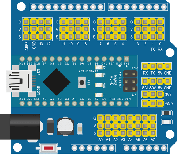
I tried updating an IRF520 MosFet part, because it doesn’t show all its connectors in the curcuit board view.
I modified the SVG using notepad++ and it’s importing “without” errors.
This is how it looks like right after importing to fritzing:
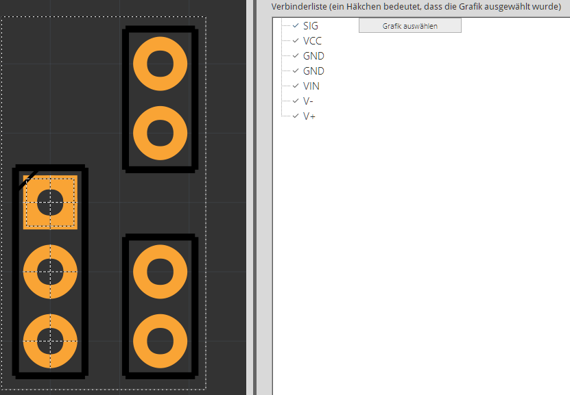
However, the pins for V+, V-, VIN and GND are assigned to something that doesn’t exist.
I somehow can’t fix that by using the “select graphic” button as it won’t show the dotted lines after clicking on the correct circle. (scrolling through the layers using SHIFT+MouseWheel)
I’m using fritzing 0.9.4 64bit on Windows10 Pro build2004 64bit, but also tried 0.9.3 64bit.
Post the svg file (you need to add a .fzp as in file.svg.fzp in order for the forum to upload it correctly, upload is 7th icon from the left in the reply menu) and I will have a look. The connectors are likely not defined correctly. The .fzpz file you are attempting to add the svg to would also be useful.
Peter
Hi vanepp,
thank you for looking into it.
I’m new to this forum, so I can only have one file/link per post. I’ll have to split it.
This is the original part:
IFR520 MOS module.fzpz (22.9 KB)
This is the modified part:
IFR520 MOS module with terminals.fzpz (23.7 KB)
And sorry, I’m too much of a noob to upload the svg-file here It always says “couldn’t determine the file-size” on any .svg or .svg.fpz file I tried.
So here’s the svg-file in my dropbox: