Quantcast
Channel: fritzing forum - Latest posts
Viewing all 31203 articles
Browse latest View live

Custom Shaped PCB crashing output

$
0
0

Every time I try to generate an extended Gerber PCB, fritzing just sits on screen showing nothing.
However, if I go into finder (OSX 10.14.2) I find all the files except for the drill file.
Is there a log file anyware I can check to see what happening or does anyone know of a walkaround/fix for this?

My version of Fritzing and my operating system:

Frizing 0.94
OSX 10.14.2kitsune badge.fzz (31.7 KB) Screenshot 2020-02-09 at 12.05.51
Please also attach any files that help explaining this problem


SK6812 RGB LED parts

$
0
0

Is anyone working on Parts for the SK6812 range of RGB LEDs?
I’m i need of the 3030 package, 4020 package and the mini E package please.

H-Bridge with L298N motor driver

$
0
0

Very detailed and useful for demonstration, thank you!

Henry

Arduino Nano I/O Shiled

Using property names in part creation

$
0
0

Not necessarily breaking code changes, there is capability to check the Frtizing version number in a part and apply previous behaviour to parts so as to not break older parts. We just have to keep that in mind with non compatible changes.

True, and that is what I would like to avoid. At present parts in core are different sizes, what I would like to see is as you say is consistent size / spacing rules for parts in core (for those not wanting rules, anything goes in user provided parts because there is no way to control it, but we have control of what gets added to core parts.)

Color is another option. A change to the graphic standards for pin names would I think be another way to do the same thing by making the color of a part pin a different color than that of the wires. I don’t know if that is true at present though, or if it would be enough.

Peter

Custom Shaped PCB crashing output

$
0
0

If you post the .fzz file of your sketch (which will include the source of your part) I’ll have a look. I’m not all that good at custom shapes, but there are others here that are.

Peter

SK6812 RGB LED parts

$
0
0

A quick look turns up a data sheet with a single package outline.

but not any of the others (nor is it clear which package this data sheet is for.) If you post a pointer to data sheets for the packages you want it is easy enough to change one of the current led parts to match.

Peter

RFID RC522 module part for 13.56 Mhz Card

$
0
0

Great job! I could use this pretty good.

Henry


Custom Shaped PCB crashing output

$
0
0

Thanks, the file has already been included in the post!.

Arduino Nano I/O Shiled

$
0
0

Something ugly has happened to your .fzz file. It is not rendering correctly for some reason:

The shield board is missing completely (although showing in schematic). The power plug has been replaced with the IRF520 module, and the icons in temp are wrong. Did you edit the .fzz file by chance? I’ve never seen a sketch like this before … I’ll have a look at the .fzz file and see if I can tell what went wrong. On an unrelated style issue, I would normally do the connections like this (on the fc-51):

so that it is obvious that there are three wires in the bundle at a glance and where they connect to. Either way will work, but I prefer the connections be obvious at a glance.

Peter

Custom Shaped PCB crashing output

$
0
0

So it is. I’m obviously going blind in my old age. I’ll have a look.

Peter

SK6812 RGB LED parts

Doit esp32 devkit v1

$
0
0

is there a improved-improved version of [DOIT Esp32 DevKit v1 improved.fzpz]?

Custom Shaped PCB crashing output

$
0
0

Thanks, I was reading the post notes and spotted it requesting the file for support help request.

Arduino Nano I/O Shiled

$
0
0

Owh, its weird that the parts are scrambled all over the sketch, same goes when I reopen my fzz.

Henry


SK6812 RGB LED parts

$
0
0

Still problems. The 4040 version has no SMD pad dimensions, it has the pitch but not the size of the pcb pad it connects to.

There is a mini data sheet here:

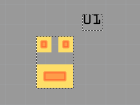
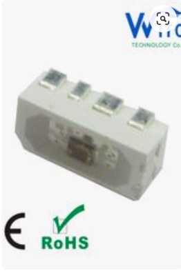
but it doesn’t have a recommended pcb footprint, and is odd enough that the foot print must be correct to avoid shorts on the pads (and the pads may need to cover the entire pin for heat dissipation reasons.) It also doesn’t agree with with the mini image you supplied (which in turn looks to be for a connector, not smd, it looks like the pads are above the plane of the board and won’t connect for SMD soldering.) So still not enough data to do anything. I need the sizes and positions of the copper squares for pcb for each package like this (from a different led):

Capture3

each square needs x/y position and height and width to know what size to make the pads. They are often also used for heat dissipation and thus need to be of sufficient size.

Peter

Doit esp32 devkit v1 30-pin

$
0
0

Does anybody has a friting part of the esp32-wroom Doit esp32 devkit v1 with 30 pins???
It’s a little wider than the esp8266 wemos d1

SK6812 RGB LED parts

$
0
0

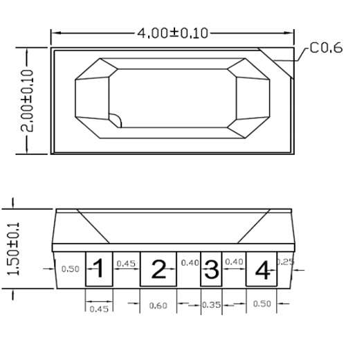
The pads marked 1 - 4 on the 4020 are SMD pads. The diode looks strange because its a side exit diode and not a top exit diode.

Pad 1 0.45mmX0.6mm - DIN
Pad 2 0.6mmX0.6mm - VDD
Pad 3 0.35mmX0.6mm - DOUT
Pad4 0.5x0.6mm - VSS

Screenshot 2020-02-09 at 16.46.55

Doit esp32 devkit v1

$
0
0

No. so far what you see is what you get. Improved in what way?

Peter

Doit esp32 devkit v1 30-pin

$
0
0

Is this the 1.1 inch spacing type? If so I made one some years ago (as I recall there are .9in 1in and 1.1in models of these.) If not it is easy enough to modify one of the existing ones if you provide a datasheet to for the board.

Peter

Viewing all 31203 articles
Browse latest View live


<script src="https://jsc.adskeeper.com/r/s/rssing.com.1596347.js" async> </script>