That does for the 4020 version, how about the mini? Is it SMD or does it want a connector (which is what it looks like?) If it matches the adafruit data sheet, which way are the pads oriented? It isn’t clear if the footprint data is looking from the top or the bottom (and that matters to the footprint.) I don’t have one to look at to tell which way it should be. The pcb footprint needs to be from the top looking down as the LED will attach to the board.
But what would older code do with a part from the updated library that had the newer version number? It would not know how to handle it, and likely not work. From the user perspective, the library is now broken. You would have to maintain a complete copy of the older version of the parts library until everyone (which never happens) is using the newer code that understands the new version.
The version number by itself supports backward compatibility. But not forward compatibility. The only way I see to do it, without breaking things for existing (non-upgraded) users, is a separate ‘version 2’ library repository that the new code would look for on install. That would start as a clone of the existing library, but then have the changes proposed incorporated. Either in bulk, or over time.
EDIT: Or a version 2 branch in the same repository
Ahh sorry, I mis understood. Its actually got legs where there should be pads on the base. It is designed to be soldered poking through a hole from the underside of a pcb.
Top down pinout
1 (Top Left) = DOUT
2 (Bottom left) = VSS
3 (Bottom right) = DIN
4 (Top Right) = VDD
All legs stick out 0.68mmX1.34mm with the exception of VSS which has a 0.34 chamfer on the outer corner.
1 big issue i have found is 2 conflicting mirrored pinouts.
Well my first fear is unfounded , I was wondering if the no pcb in the Nano shield was having an unexpected effect, but it doesn’t appear so. It looks like something on your system corrupted the fzz file when it was written. I recreated the sketch and it appears to load fine now:
Several things to note here: the red circle around the fc-51 is how I would route the wires to make the connections clearer. To do this I clicked View->Set grid size and reduced the grid size from the default .1in to 0.05in:
to allow closer spacing of the wires. The vertical layout of the nano shield makes the breakout more difficult, but with the 0.05in spacing you should be able to have at least a stub on the servo connector which shows where the wire terminates. The other thing of note is I have less parts in the mine parts bin (the red cirle on the right top.) That is because the barrel connector and the fc-51 are both now in core parts. You probably need to click Help->Check for updates to update the parts repository to the current version. In any case here is the .fzz file which now loads correctly for me:
Current part, Fritzing version 0.9.4 (current version) with Edit pin labels true set in the fzp file. Because of Fritzing version 0.9.4, the code acts as now, substitutes the boiler plate svg (which breaks header parts for instance.) as now and the part works. New part, Fritzing version 0.9.5 (not yet released) uses the new mechanism to find the position of the labels (which is I suspect why the overlaid svg) and does not break if applied to a header, and does not break older parts that do not recognize the new functionality because their Fritzing version is less the 0.9.5. If the version number is less than the Fritzing version the change is made in (likely not 0.9.5 since this work hasn’t started yet), the current code is used, if the version number is later than that, the new code is used (a simple if statement and some additional code bulk because of the two code streams, but easily doable.) If the part is in core parts, the obsoleting mechanism will allow the new part and new functionality to work by swapping out the old part (or not as the user chooses, as it should be). The designers thought ahead when designing the code base and similar things are already there (the format of parts has changed over the years such as the nested copper layers in pcb, but old parts still work fine in old sketches.) We need to be careful to test old parts when making such changes but it should be possible to do if we are careful. No need for different repositories (which is a maintenance nightmare.) unless I am missing something.
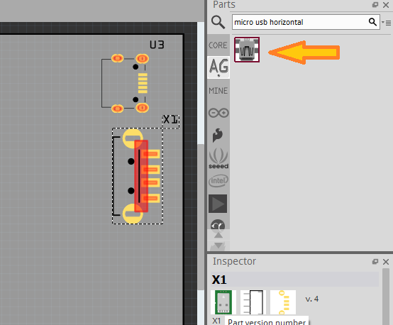
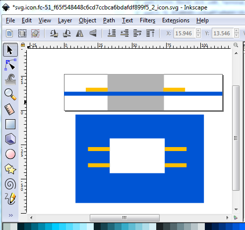
It is entirely possible this is the same part one with view from the top and the other view from the bottom (of course with no labels to tell you that.) This is very common (and very frustrating) in data sheets. I think illumination has struck, this looks to be one of the so called middle parts (usually USB connectors) where the body fits through a hole (or rectangle in this case) which the led drops in to. That is a problem in Fritzing, because it doesn’t easily support rectangular holes (and as far as I know neither do the inexpensive board houses.) Essentially this (the top image is side view and the bottom the board in blue the pads in gold and the hole in white:
the hole is the hard part, both in fritzing and to get someone to produce it I think. A circle is easy both in Fritzing and for the board house, but I expect it will cut in to the pads to be big enough to fit the square body. This might work (the pads are to scale from the data sheet above) although you are losing about 1/4 of the pad area to the hole(which has to fit the corners of the rectangle as shown):
Thats interesting that they cant handle square holes, I was looking to add round (well ovalish) in a future version.
Thank you for working on this for me.
That is not quite the scenario I was trying to describe. Let’s try a hypothetical example. That family of parts I am working on could be described to Fritzing in a much more condensed format. It is really only one part with selection of different image files based on the selection of the size, polarity, and footprint. Those 16 fzp files I created are identical except for:
module id attribute
referenceFile attribute
title
property values for ‘size’, ‘pcb pad’, ‘variant’
image attribute of layers element for each view
Those are the ONLY differences.
So, suppose I propose a change to allow that to all be described as a single part. One moduleId, referenceFile, title. With an adjusted element and attribute syntax to supply and select all the alternate information. Like this.
There are many other ways of implementing the same concept. This is not optimized in any way, just a quick description of what I can visualize, and should be an obvious extension of what is currently being used.
Since it jumped out at me as I was writing the above, here is an extension/variation I like better, taken from the substitution done for spice entries. It reduces the duplication even more, by getting rid of the separate conditional layers element entries for each view. Closer to the current usage.
The newer code would see that as equivalent to 8 parts in the older format. 16 parts, if I had added in the polarity variation that only affects the schematic view, but the point is, what would Fritzing 0.9.4b or earlier do if it saw that in a library part? Regardless of the version number in the part? When the user tried to drag it from the parts library to a view.
This particular case could be handled by the library update process. It could automatically generate the 8 or 16 parts, and store them in the parts library in the older format, instead of this condensed version that is easier to maintain. Easier because there is only a single copy of all of the rest of the part information that is the same, and should STAY the same, if a detail changes. Like adding another tag. Or spice information. Which would also need to support some form of the conditional syntax.
Very likely screw up. It is too large a change from the current implementation (which assumes a single part to a single moduleId by and large, with variants having a different moduleId.) I’m not being that ambitious , only considering things I think can be fitted in to the current constraints. The idea of an external script or program that converts this format to the multiple standard parts is probably the way to go here as that won’t break backwards compatibility. This does however bring up a good point, I hadn’t considered, a part that depends on new functionality won’t work in an older version of Fritzing which may be a problem. One way around that is to advise the user to upgrade to a newer version, but I don’t know if that is acceptable or not. If I am lucky, there might be a test for version of part higher than current version of Fritzing, that triggers a warning the part may not work, but I don’t think so.
I am not anywhere near a pcb expert, I make very few boards, but this discussion has come up before and generally odd shaped holes in boards need gerber layers Fritzing does not generate and most of the cheap board houses don’t support.
Any documentation around on the variations for the current and older code? This comes from what should I put in the fritzingVersion attribute for the set of parts I am working on, to make them most widely usable? I was going to put 0.9.4b, since that is what I am using, but there is nothing special, that I know of, that should prevent them from being used with older versions of Fritzing. I saw reference to the change of color for silkscreen. Will the wrong color break older versions of Fritzing? With minimal work, I can test against 0.9.2b, and I think 0.9.3b using an appimage. But that is not very fine grained. I believe there were multiple smaller releases that all used those prefixes. The part intended to be obsoleted is marked with version 0.2.2.b.03.04.2550.
As usual no documentation that I am aware of. I usually use 0.9.4 as the Fritzing version because that is what it was made on. AFAIK there is only special code for some older versions of Fritzing where functionality has changed in the latest version and there haven’t been any such changes that I know of in the last two versions so your part should work in older versions. I don’t think there are a lot of older versions around any more. Some of the Linus folks are on 0.9.2 because that is what is in the app stores. The main change there is no parts editor I think (and possibly not copper1 within copper0 as well) which were added in 0.9.3b.
A fairly easy one, your logo svg is invalid. You likely have the original svg, I recovered it from the .fzz file using the instructions here:
That said, the svg has multiple paths in it. A logo svg can only have a single path (created by combining paths in Inkscape.) I have never actually been able to get this to work I don’t know enough about paths, @opera_night is the expert here. He has several how tos on this subject in the tutorials section. There are also a number of bugs in the gerber generation code Kjell fixed at least 5 of them in the 0.9.5 dev version a couple of months ago (but it isn’t released yet.) A search in the forum search bar for pcb logo will turn up a bunch of posts too.
I haven’t been visiting this site much - received email about this post so… following up…
Your posted file was not usable for me. If wanting my help with Graphics, post the Graphic file (the SVG. Change or, add the .SVG to .FZZ and it will upload).
Won’t repeat what I’ve posted (see my other posts as “vanepp” stated).
Attached are:
a. funky.fzz; the Fritz file with the SVG loaded.
b. An SVG you can use as a baseline in your preferred graphics program.
Pay attention to; layers and paths (may not upload as svg - seems Fritz changed site stuff and the svg with .fzz extension wants to upload as an svg - perhaps replacing .fzz with .svg will still work…?
The SVG contains the shape with a Graphic face and Text. Also includes shape on the Silkscreen.
Added dumb circuit part to enable exporting gerbers…
Well that is ugly. The new forum software doesn’t appear to accept svg as fzp files as the old one did. It appears to recognize it as an svg and tries to upload it as an svg, unsuccessfully. To recover the svg above you need to both remove the .fzp and edit the file and remove the
from the first line with a text editor. The “remove” appears to fool it in to thinking it is an fzp file. How inconvenient! Although I suppose for email notifications working again it is a smallish price to pay I guess .
Exactly. But your earlier post about a new specification document would have allowed it.
For that particular case. I actually have some python code that comes close to doing just that. Because I have a different family I would like to do similar extension to that would be something like 144 fzp files. But other changes that fit in the part file format revision might not be so easy to work around.
That idea for a revised part format document needs some additional constraints to prevent this situation.
I doubt it. Not all users have the right knowledge to upgrade to a version that is not provided by the standard software management programs.
Or in the case of Fedora linux, what the package manager has. Unless you meant app store in a more general sense.
That possibility, or worse, silently failing, is why I want to know what fritzingVersion to put in the parts. My understanding from your usage descriptions says I want to put the lowest possible version that makes sense. In other words, the fritzingVersion value should be first/lowest fritzing version that the part is compatible with. Lower run time versions beware. The specified version or newer can safely process.
Again with lack of documentation, I’ll need to do some testing, to see what Fritzing does when that version number is higher than the currently running program. I can clone one of my parts to force a 0.9.9 version into the library, and try to run with 0.9.4b, or run 0.9.2b code against the library with 0.9.4b version parts.
@KjellM Do you have a suggestion where to dump some initial discovery information that will be collected doing that? Or better, reference to documentation that says what it should do.
Or maybe I can short cut the testing, with good confidence.
% grep -ri "fritzingVersion" * on the fritzing-app repository only found references in a few files. Ignoring the resource files, which are just data, most did not work with value variations. The exceptions are:
tools/scripts/resetversion.py does a bulk replace to change version numbers from 0.8.6 to 0.8.5 (probably for the schematic template change seen below). src/autoroute/panelizer.cpp handles GroundPlane::fillTypeGround only for versions before 0.7.0 src/sketch/pcbsketchwidget.cpp only shifts pcb vias and holes after 0.7.2.b
‘src/model/modelbase.cpp’ has alternate processing for several cases. Quoting the comments:
// with version 0.4.3 ratsnests in fz files are obsolete
// with version 0.6.5 traces are copied to all views
// with version 0.7.6 mystery part spacing implementation changes
// with version 0.8.0 flipSMD is horizontal
// with version 0.8.6 we get a new schematic template
// with version 0.9.3 we don't have to worry about reversed wires
None of which seems to overlap with my parts. I can safely set the version the same as the single part I want to obsolete. 0.2.2.b.03.04.2550
And that points to another small project. The part check (or other validation code) should check the fzp and svg content against the rules for the specified version. Even better, parse against all rule sets, to figure out what the (minimum) version should be. Bonus if it can report the part content and rule that results in not being compatible with an older version.
From that search, no check or warning. It just silently does alternate processing for a few cases. Which could of course result in real error messages, or unexpected output, if the content contains features that do no match the specified version.
I did not see anything related to that in search results.
A new spec isn’t in the cards, my intention was to specify some of the things that aren’t clearly stated in the part file format such as stroke-width on lines in the svgs, length of connector pins, using the minimum space possible for parts to provide more room (and consistency between parts in core) to constrain already working function to a smaller more consistent subset, not add new function. My intent is to get agreement on a desired or at least acceptable outcome and then work on fixing the current core parts to match, which in itself going to be a lot of work. Some parts in core parts are just plain broken right now. Some are odd sizes, that is more than enough work for some time to come. Many of the changes I intend are already in places like the template files (which are also wrong in that they are 72dpi with px as dimensions currently and scale incorrectly in Fritizing if used as a template in modern Inkscape versions.
I think silently failing is unlikely, unless the part is
invalid. I think (but don’t know for sure) there are
relatively few special cases. I believe separate copper0 and copper1 (as was the original standard) is about the only one I’m sure of. I’ve made lots of parts and other than obvious invalid xml errors never had one fail by tripping over a special case in the code. There are a bunch of special cases around making breadboards, but they are specific to how a breadboard needs to operate (always on the bottom for instance.)
You should be able to just create a part as an fzpz file, and change the version and load it. No need to put it in core parts. The only difference with an fzpz file is that is is in the mine parts bin, not core otherwise it is processed the same.
Someone lately referred to the package manager (possibly in Fedora, perhaps one of the others) as the “app store” and I reused the term probably incorrectly.
It may be that the original code was just left in as copper1 not a group of copper0 still works fine and is useful for things like edge connectors that need different pads on top and bottom of the pcb which the copper0 inside copper1 can’t do.
I looked at the SVG file and offer couple of things to consider:
For graphic drawings, you can do most anything BUT, to be compatible with Fritzing, you CANNOT do Many things - SVG is particular about how it does the Math, how it interprets intrinsic-subtractions and, compounding that with how Fritzing manages/interprets SVG… Well best to say KEEP IT SIMPLE. Meaning, if you have, for example, things like a Head and Ears, it’s best to draw them as a contiguous line, not composites of Head and Two ears…
Quickly redrawn to give you the idea… below
You won’t have much success with crossing lines and sharp pointed-ends with micro-fractional distance between lines…
For a complex Silkscreen, consider doing the graphic and using the ‘Logo’ part and not Silkscreen.

 , I was wondering if the no pcb in the Nano shield was having an unexpected effect, but it doesn’t appear so. It looks like something on your system corrupted the fzz file when it was written. I recreated the sketch and it appears to load fine now:


 project. The part check (or other validation code) should check the fzp and svg content against the rules for the specified version. Even better, parse against all rule sets, to figure out what the (minimum) version should be. Bonus if it can report the part content and rule that results in not being compatible with an older version.