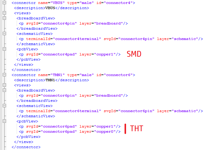
You are missing the copper0 layer everywhere and thus won’t get through hole anywhere. The slots in the pads will also not render (Fritzing can’t do tabs, nor generally can the board houses.) This tutorial explains how to get mixed through hole and SMD parts (although it is painful assuming you are using Inkscape):
The pins are all described in schematic and if you hover over a pin in any view in the DOIT Esp32 DevKit v1 improved.fzpz file above (and I expect in the original as well , because I am unlikely to have done it.) If you post a screen shot of what you think is missing I will look further. Parts update works fine, no one much (including me) is submitting parts to github which is currently the only way they get added to core (for that matter not a lot of people are making parts at all any more …) If you are running Win7 and 0.9.3b parts update is broken and you need to upgrade to 0.9.4 to get it working again. In my case I haven’t figured out how to keep the three repos in sync so don’t even try any more. There are a lot of variants of the esp32 because there are a lot of slightly different versions (I have made or modified more than half a dozen of them.) If you own an odd board you want a part for it and by and large we have obliged. I haven’t seen a new request in a couple of years I don’t think. This was likely the last one and it is 2 years old now.
I read the topic… Yes, the different copper0 & copper1 is now old. I tried that too.
But, it’s not mandatory to keep the “same pin svg” with “same name” for THT.
Because, I create/edit part via part file (.fzp), and there, the svgId can be edited to different names for copper1 & copper0.
@vanepp@opera_night Thanks all, I will go back and redesign the source SVG file.
Has someone worked on an updated pcb design guide yet?
I did try to combine the vectors but obviously something went wrong.
Thank you again for ripping the design apart to find the issues.
I will update this when I have a redesign that works.
Thank you again.
I agree that we need a good reference documentation for the parts format.
I even see this documentation as a precondition, before we can even think
about improving the parts format.
Confirmed that it IS necessary to change the family property in the obsoleted part. If it is not changed, inspector offers it as a selection in the drop downs for other parts in the same family. Or more accurately, includes the property value from the obsoleted part in the drop downs for any matching property name, which when selected switches to the obsoleted part.
So should, but does not. In version 0.9.4b, commit c595162a1d06
Technically, it is not necessary to use that prefix I bulk sanitized previously. All that is needed, is to have the family of the obsolete part different from the family of any part that is not obsolete.
There was a sequencing problem in the old part, so I needed to add a replacedBy attribute to most of the connections as well. Doing the replace go the schematic view right. There were bogus wires added for (it looks like) all of the connectors with the replacedBy attribute. The way the showed up, it was easy to bulk select and delete those. Then a move (jiggle: move off and back) of the part on the breadboard got it to reconnect to the proper wires. That ended up deleting a bunch of traces on the pcb view though. Moving the part found bogus doubled pads under most of the connections. NOT the first couple of pins, which had a full replace. The names changed from “pin1” to “pin 1” and “pin2” to “pin 2”. Pin 3, 4, 5 were correct, and did not need replacing, but they did get the bogus pads. Starting at pin 6, all of the connector were being replaced by the same name, because the connector number was wrong (one off). Replacing “pin 6” with “pin 6” looks like a good opportunity for something to break. Doing the substitutions using the id instead of name got the the same (or at least very similar) result. Again though the replacements were overlaping. Change connector8 to connector7, change connector9 to connector8, etc. I also tried modifying the new part, changing the connector ids so that they do not overlap with ids in the obsoleted part. FritzingCheckPart complained about that, though I think it is technically valid (I changed the “connector” prefix on all of the connector ids to “cnnector”). Did not help though. Results looked a little different but basically the same problems. Just a couple of different traces on the pcb were messed up.
So either I am missing something for properly making a part obsolete, or there is a problem with replacedBy for connectors. I expect it is the same code, but to be complete, I said “no” on the initial replace requestor, then did the update from the part menu. Same results.
At some point, this documentation is as important as the implementation of the app. If enough parts just follow it, we will have to adapt the code. Of course it would have to be in document management (meaning, git). But with wiki, do you mean public write access, bypassing code reviews?
I’d like to automate syncing the documentation to the app and the website. With a public write access, this would require permanent monitoring…
@KjellM The wiki was an idea for collaboration, collecting, merging, referencing sources for related information. If needed, snapshots could be copy/pasted to more stable locations. That said, the wiki is itself a git repository, so it is under version control too. It is possible to git clone the wiki, just like the main repository, and push changes back. To really mess it up requires a lot more than just write access. An owner could force push completely new content, throwing out all of the history. Standard git commands work normally on the cloned wiki repository, so commits, when/who did, what changes are easy to check.
The parts are up. Clone https://github.com/mMerlin/fritzing-parts.git and switch to the “8x8_led_matrix” branch. The original (obsoleted in that repo) part was LBT2088AH. The new parts are «xx»mm_8x8_dot_matrix_«xxxx»_cathode_led_display«_narrow_pad». Once the database is regenerated, a search for “8x8” will find them all, and not much else. As mentioned a few posts back, the outdated part update process seems borked. At least for that part. Working on gathering the information for reporting that as a bug, but it is 4AM my time. Need to shut down for awhile before I start making silly mistakes.
I know how github wikis work . Maybe I didn’t understand you suggestion about using the wiki, because that is what we already have; https://github.com/fritzing/fritzing-app/wiki/2.1-Part-file-format, you have contributed to that before. I am suggesting to raise the importance of this document: Making it the master for documentation on fritzing.org and the desktop application, and having it more complete to serve as specification.
No matter the Drawing program used, some shortcomings and work-arounds will be required to use results in Fritzing. Thus, you can use Inkscape/others - just need to invest the time and interest to get there…
Below shows crudely drawn shape (I like cats) done in Inkscape (and loaded into Fritzing).
I did NOT do anything such as making it a Path. What you see is all that was needed.
I did not do the Silkscreen drawing or any details… that may have required making paths but, you get the idea - it’s about do a little, see if it works/get-it-to-work and move on to the next part of the drawing… eventually, you’ll know what work/doesn’t-work…
The Drawing Programs I’ve used to make PCB with shapes and cutouts are:
Inkscape
FreeCad
EZDraw
Boxey
OpenOffice (the embedded drawing program)
Gravit
Paint
PaintBrush
CoralDraw
and perhaps another handful. Look for my posts… But, recognize that most software changes some aspect that previously worked but, no longer - thus, requiring more time and trials…
Welcome aboard. Indeed it does not appear to exist, so I made one (easy for me, less easy for you likely.) While it is correct as a Fritzing part, the pcb footprint may not be correct (the data sheet is unclear, and I don’t have a part.) So you need to print out the pcb footprint at 1:1 scale and check it against a real part to make sure it is correct before ordering boards. The holes are 0.035in (the pin should be 0.030in according to the data sheet) but it would be a good bet to try the part in a 0.035in hole before ordering boards. Down load the .fzpz file and File->open will load it in to the mine parts bin.
and for the smd pads only defines copper1 in the connetor but for the through hole portion defines both copper1 and copper0, which also works (as long as you don’t need different connections on different sides of the board in the same place.)
Lastly… Perhaps I shouldn’t post this but, I figure eventually many folks look into alternatives to Fritzing. My favorite has become KiCad. Though a robust program, individual aspects of it are as simple to master as is/was Fritzing.
Below shows a PCB shape done in FreeCad (exported as .DXF) and imported into KiCad’s PCBNew program.
Could have drawn it entirely in PCBNew (it has very basic draw tools).
Screenshot shows PCB with imported DXF and the 3D-View displayed… Click image to expand full view, if needed.
I would expect that that may break (but doesn’t necessarily seem to, if that is what was done) old sketches. Someone (when we find Someone of course ) needs to figure out and document the obsoleting stuff. From my single experience a couple or 3 years ago I suspect there are problems, but have never gotten far enough ahead to get back to it.
Thus the "(note the weasel word ) " comment above. I had a feeling there are problems in this area, just not the time to look at them.
From what I remember about how the part I tried screwed up I’d bet on either bugs or someone didn’t know how to do the replacement correctly (with my bet on bug )
I’ll grab a copy and have a bash at it.
This is why I originally suggested revising the parts file format document. At present it is spread out between the template files (which as noted are wrong) the parts file format and the graphics standards with large grey areas that would be (in my view anyway) tightened down to make parts more consistent in appearance. I think none of it has been revised since the early years of Fritzing as well (certainly the templates.)
edit:
I’m liking this idea, that is probably a good place to start as it is more free form than the documents. If we can get that together and agreed on it should be able to drive the changes to the documents and provide context to why the document changes were made. I’ll start documenting the things I consider when making a part as a start to this (and probably post it in tutorials here, in text because pdf is yet another thing I haven’t done .)

 . Maybe I didn’t understand you suggestion about using the wiki, because that is what we already have;

 ) needs to figure out and document the obsoleting stuff. From my single experience a couple or 3 years ago I suspect there are problems, but have never gotten far enough ahead to get back to it.