Quantcast
Channel: fritzing forum - Latest posts
Viewing all 30856 articles
Browse latest View live

IC Component CReation

$
0
0

Peter

I did check the footprint and it is an exact against the actual chip. However, I started to create a new pcb layout with the chip. and it seems to work ok until I ran the DRC (Design Rule Check) and I am getting all route to and from the chip reported as Overlaps. I tried a different chip from the library and I am getting the same result so it doesn’t appear to be a problem with PIC24FJ128GA204. I did try really thin wires but it still reports Overlay errors. Any idea why I would be getting these?


IC Component CReation

$
0
0

You need to set the grid size down to be able to position the traces far enough apart to pass drc. I’m using 0.01in (down from the default .1in) here and drc passes. You can also relax the default drc rules a bit for really fine pitch SMD but that shouldn’t be needed here.

I had to tweek the position of a couple of the right side traces a bit to get DRC to pass (if you click on the error in the DRC window it will show the conflict in red to tell you where to move.) If that doesn’t fix it, upload the .fzz file and I will have a look.

Peter

Part update pcb view mess, possible corruption in sketch

$
0
0

I think the pin rows of the original part were not an exact multiple of .1 inch apart. Which was why I had to initially fiddle with the breadboard positioning to get things to connect. Then the new part was at exactly 1800mils row spacing (if I did it correctly), so needed to fiddle with the positioning again. Though simply turning snap back on, and jiggling the breadboards would probably have got back in alignment.

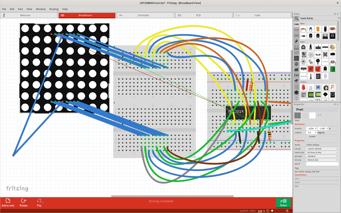
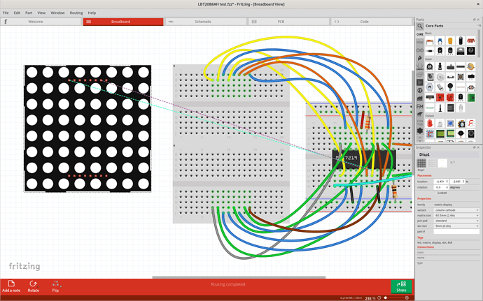
Confirmed that with 2 “tiny” breadboards positioned at exactly 1.5 inch vertical offset, that the new 60mm LED Matrix part connects with no issues. Whether the align to grid is on or off. Tested by having align turned on, grid size 0.1, positioning the breadboards, locking the breadboards, then positioning the LED matrix both with align to grid turned off and on.

However, I just retested from scratch using the existing master branch and old LBT2088AH part. It too connected just fine, with or without align to grid, when the “tiny” breadboards were positioned and locked at 1.5 inch separation.

Back to my copy of the “LBT2088AH test.fzz” file, turn on align to grid, grid size .1, tweak the breadboard position to snap to grid, lock them, move the part off, then back on the breadboard, connects with no problems. Easily with align to grid on, a little fussy when turned off.

I probably turned it off exploring where to position the resistors. The side bus connections on the “half+” breadboard I use are offset horizontally from the core groups. Apparently by .05 inch. That makes connecting a resistor from the ground or power bus to a pin in the center groups tricky. It will often snap to the wrong side. So turn align to grid off, and carefully position where it connects properly. Or rotate to one of ±84, ±96 degrees. That is cleanest, but can break the associated connection on the schematic view.

Next, I cleaned up that copy, replicating approximately what you did. Saved that, exited, switched parts libraries (actually just changed the checked out branch in that case), rebuilt the parts database, and did the update again. The breadboard view initially looks cleaner. A couple of bogus wires, and ratsnest lines, where a couple of the updated part pins did not reconnect to the breadboards.

Verify that align to grid is on, set to 0.1 in, then jiggle the LED matrix part takes care of the ratsnest lines, but also show a lot more bogus wires. Moving the part away from the breadboard shows.

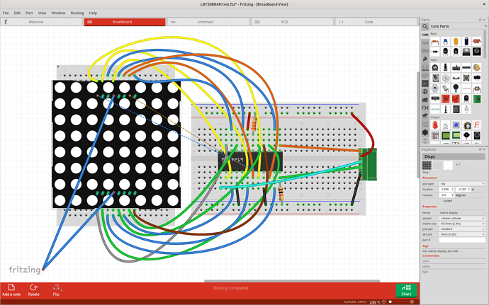
The initial ratsnest lines were actually the best part. A simple part move fixed them. Still not too bad. Just move the part away, delete the wires, and move it back. Or not. Deleting the wires did not create ratsnest lines. Checking the schematic view shows the connections all still in place. Moving the part back into position on the breadboards got rid of the 2 ratsnest lines again, and the breadboard view looks proper. But the pins are not really connected. Moving the matrix away from breadboard again still shows only the 2 ratsnest lines. Though schematic view looks just fine, and moving the part there drags all of the wire connections along with it. Pretty sure there is a bug in there someplace. Quite possible a nest of them.

2 pins did not connect at all on update (correctly) getting ratsnest lines to where they needed to go. 2 created bogus wires to nowhere, and the rest create bogus, almost zero length, wires where they should have just connected to the breadboard. The only pins that seem have really been connected (internal program circuit connections) were the 2 rats nest lines. Otherwise, deleting the wires should have converted to ratsnest lines.

Opened your LBT2088AH-test-new-breadboard.fzz, visually saw the part move slightly on update. No visually bogus wires, or ratsnest lines, but moving the part off of the breadboards shows that all of the pins are connected to the breadboards with new wires. Deleting those wires did not create ratsnest lines. Schematic view has all of the proper connections. PCB view looks a bit better than mine, but there are a lot of red circles where traces are not connected to anything. Moving the matrix part shows that ALL of the top layer traces are disconnected. The bottom seems fine. That points to a possible copper0 / copper1 problem in the update process. Moving the part back into position did not reconnect. Moving the part away, to be able separate the connection pin and unconnected trace, I could move the open trace end and get it to reconnect. Move the part back where it belongs, and rules check passed too.

AND doing the fixes on the PCB view also brought back 5 more of the ratsnest lines on the breadboard view. 7 top layer traces were fix on PCB view. Checking pin numbers, it is all of the PCB top layer traces that have ratsnest lines on the breadboard view. 2 were there to start with.

I think we are going to need to see if we can create a (or several) smaller/simpler test case, to narrow down which conditions cause problems here. The update for LVT2088AH has to work hard on the connections. There are replacedBy keys all through it, and for several different reasons. That that all top layer traces failing is a good hint for one problem.

Part update pcb view mess, possible corruption in sketch

$
0
0

While I like my theory that all was well better, that does seem to be blown. I agee the thing to do now is find the minimal set of wires that cause the problem so that ubiquitous person someone can fix it (might even be you or I one day :slight_smile: .)

Peter

I need a power supply

Using property names in part creation

$
0
0

So having the refenceFile point to the file it is in does not actually make any sense. To be at all useful, it needs to point to a different fzp file, and even then it is useless unless the current fzp file is missing references to svg files. I did not know that last qualifier was even valid.

Looking for a usb Mini B connector non smd

I need a power supply

$
0
0

There is a generic one here:

For this part pcb needs to change some. The above drawing is missing which pins are the AC side and which the DC (which matters!) With that the change is relatively trivial.

Peter


Using property names in part creation

$
0
0

I wonder if this is intended to allow reuse of svgs already in core parts (although I don’t necessarily see how?) One thing on my list of enhancements is a way to specify in the layers section an svg already in core parts so (for instance) pcb footprints can be reused. 10s of copies of the 14/16/20 dip svg as current is wasteful of disk space and network bandwidth when using a single copy in core parts makes more sense. As usual nothing has happened about this other than it being on my list of things to do at some time in the future …

Peter

I need a power supply

$
0
0

Sorry for not mentioning Ac Dc. Left 2 pins ac and right are DC

Looking for a usb Mini B connector non smd

$
0
0

This should do what you want. Since I don’t have one, and thus did this from the data sheet you should print out the footprint at 1:1 scale and check both the pin positioning, hole sizes and the pin numbering match the real part before ordering boards. As well the slots for the mounting tabs are implemented by two 0.8mm holes, so it may be necessary to cut or file the slot wider (Fritzing and I understand most of the cheap board houses don’t do slots.)

USB-mini-b-tht.fzpz (7.3 KB)

Peter

Looking for a usb Mini B connector non smd

$
0
0

Thank you very much! I will give it a shot. It will take some days to report back, if everything worked out. Don’t worry about the slots, I drill all my holen in 0.8 on my cnc and then widen the necessary ones with a drillpress by hand.

Sparkfun XBee Explorer Regulated WRL-11373

$
0
0

Sparkfun XBee Explorer Regulated WRL-11373.
The old version is in the Fritzing library. The long side pins have relocated inward on the current version. When I asked about it on their forum they said it was “in the library.” Didn’t seem to be a bother to them.
I have made three headers that I drag onto the board and align by sight and I can drag the old version over the top to check the overall footprint, then I drag it back out of the way.
Thank You!

I need a power supply

Sparkfun XBee Explorer Regulated WRL-11373

$
0
0

By “in the library” they likely meant the Sparkfun Fritzing repository on github, not core parts. That is not loaded in to Fritzing by default, you need to fetch it from github and load it (or just grab the part you want from it.) You should be able to load the part from the Sparkfun library and replace the one in core (by using delete minus) as long as they have been careful about family and variant values.

Peter


Need help with finding a library for a barcode scanner

$
0
0

Hello!

I am new to this forum, I have recently started using Fritzing 0.8.7b but I’m unable to find the library for a barcode scanner (NTEUMM) for a smart lock project that I’m currently working on, If you guys can help me find the any libraries relating to the barcode scanner that’ll be great.

Need help with finding a library for a barcode scanner

$
0
0

First off 0.8.7b is quite an old version of Fritzing, 0.9.4 is the current release and you would probably get better support if you upgraded to it. That said, are you looking for a Fritzing part for a barcode scanner or a software library to interface to it? A quick look at the NTEUMM site seems to indicate they are USB connected which generally doesn’t do well on Fritzing (few parts other than USB sockets support USB connections to other Fritzing parts.)

Peter

Searching for 3.5mm 4pin Jack YD-PJ-3566

Part update pcb view mess, possible corruption in sketch

$
0
0

Bringing references over here for a work around.

work around discover
reimplementation and testing

The apparent cause of the bogus breadboard wires and disconnected pcb traces is a slight mismatch in the spacing of the connection pin rows between the new and old part in the breadboard view svg file. The new part is exactly 1800mils row spacing the old part was off a bit. The vertical px per inch calculation based on the svg height and viewBox was (172.129/2.39568) = 71.84975 px. Not quite the standard 72. The offset between the pin rows was (151.682-21.288) = 130.394px / (px/inch) = 1.8148 inches (1814.8mils). Changing the 151.682 coordinate values to 151.288 to get an even 130 px separation / (px/inch) = 1.8093 inches (1809.3mils). That was close enough to let the part update process finish properly, while not breaking any connections in the example existing sketch, if the update was not done.
If the scaling had been the expected 72 px/in, that would have been a change from 1811mils to 1805.6 mils.
With the viewBox scaling, 1.8 inches should really have been 129.33 px.

Unable to install Fritzing in Win 10 64bit HP PC

$
0
0

Hi, just now installed the windows version code of Fritzing and tried to install it. Its is not beginning installation and no error is also reported. I had made the payment through PayPal after which i received the link and even downloaded it twice but of no help. I am trying it on a HP PC with Windows 10 License copy so no case of piracy also. Please help.

Thanks in advance

Pankaj

Viewing all 30856 articles
Browse latest View live


<script src="https://jsc.adskeeper.com/r/s/rssing.com.1596347.js" async> </script>