My Ender3 goes S G V on the JST the same as the top pic, so I guess it’s Signal, GND, V+. The 0 is probably the LED polarisation.
↧
Limit Switch part
↧
Part breadboard with gradient
It needs someone smarter at INK than me  I was thinking the gradient was under the black rectangles, but it looks like FZ deleted the gradients - I think I remember the part export svg having less nodes -.
↧
↧
Hoe to chnge the color of a LED
Hi,
thanks a lot for your answers and tips.
Yes I found a solution. I didn’t know how to handle it.
I have to select a LED and placed it on the breadboard. Now I can modify the colour.
Great tool!
↧
Newbie: first circuit, thoughs?
hi to all.
I’m totally new to Fritzing (and to arduino).
I’m trying to build a very simple NodeMCU multi-probes temperature device.
In reality, i did it again on a breadboard, I would like to replicate the same on fritzing to build a printable PCB (jlcpcb i think)
I have some issue with autorouting on Schema and PCB, but let’s start step by step, do you thinkg this breadboard would work ?

It’s very simple: a nodemcu, a DC power jack (5v, but i’ll add more parts later), 6 temperature probes connected with a JST connector. Each JST has one pin to the ground, one pin to the +5V and 1 pin connected to a 4.7kohm resistor and then to the 5V
↧
Ground Fill with gap lines
This is a big problem for me when trying to etch with a pdf.
Would you please indicate if this will be fixed in the next release and approximately when that might happen?
Thanks, Roger
↧
↧
Ground Fill with gap lines
Please note the lines do not disappear when I export to pdf or svg, both usually need to be manually edited to ensure the ground plane is contiguous.
↧
Newbie: first circuit, thoughs?
What type of temperature sensors are you using? There are multiple variations that have different requirements on how they are connected to the controller board. The layout you used only works if the sensors are 1 wire protocol devices. Visually, that looks like a 220 ohm pullup resistor, not the 4.7K you put in the post.
The 5V input is fine to power the NodeMcu board (at the VIN pin), but your layout is also using that to power the sensors, which implies that the data line (through that pull up resistor) is also 5V. NodeMcu is a 3.3V device. My quick search did not find any information to say that it was also 5V safe for the data pins. You probably need a level converter. Which might be as simple as a voltage divider and a transistor.
When asking this type of question, it helps to provided the actual Fritzing sketch file. That way some of the questions can be answer by looking at the actual part in the document.
↧
Newbie: first circuit, thoughs?
Yes, sorry for the resistor, it was a mistake, the correct one is 4.7kohm
Im using a bounch of DS18B20 in parasite mode, the breadboard shown is with the old wiring in normal mode. Parasite mode simplify the wiring a lot.
For the power: i have a 12v power supply, then i’ll put a buck converter for 3.3v. biggest issue is: as i would like to share this design as much as possibile with another 2 boards that needs a 5v and 12v rispectively, what do you suggest? I need 3 different buck converter?
Something more simple than a buck converter? Tension regulater are way too hot
↧
Newbie: first circuit, thoughs?
One possible simplification. The information I have says the DS18B20 works from 3.0 to 5.0 volts. If the 3.3V line on the NodeMcu can provide enough power, run the sensors from that instead of from the 5V input used to feed VIN. That will get the sensor data line to the proper 3.3V.
I have seen some information that says parasite mode can be trickier to get working reliably. I looked at it (with those sensors actually) for one project, but for my case there was no real benefit.
If you can run the sensors from 3.3V on the node mcu, you can ‘share’ the 5V with this. 12V is going need separate power. If this is going to be physically connected, the main power can be 12V, with a 5V buck converter for VIN here and the other boards, and 3.3V only supplied to the sensors by the NodeMcu board. Not really enough information to say that will all work.
↧
↧
Newbie: first circuit, thoughs?
In parasite i’ve tested 5 sensors at the same time (daisy chained) with about 2 hours with no issue
Today i’ll try with 10, the maximum i have to support
But i had a lot of issue with autorouting, both in schema and PCB, the autorouting makes a lot of wrong connections (like connecting all sensors pins together, the gnd to 3v and so on, thats why i’ve posted the breadboard, just to have a confirm that wires are ok)
↧
Newbie: first circuit, thoughs?
We can not tell if the wires are really correct just from an image of the breadboard view. Those “wrong connections” can be from the (sensor) part having an error in which pin is ground and vcc on the schematic versus on the breadboard view. It can also be from a crossed wire on the breadboard view, even if that was later corrected. People have seen errors like that, where Fritzing will “remember” a connection that was later changed. This issues tends to get worse if connections are created in multiple views, instead of everything done first on one view, then just filling in wires to match the ratsnest wires in the other views. If the problem started from the last cause, deleting all wires, in all views, then recreating in just one view can fix things.
Again, the full sketch file is needed to start doing anything more than guess. You said “autorouting”, which in frtizing is something different than what your latest description implies. I think you meant that the ratsnest wires in the other views are not going where you expect. That is not autorouting. Autorouting is a tool to layout the traces on a pcb, so that they do no conflict (cross) on the same side of board. It often does not do a very good job, but is quite separate from where the ratenest wires/lines are placed by Fritzing.
EDIT: since the breadboard view of those sensors are symmetrical, it could also be that one or more have been flipped horizontally, which would cause ground and vcc to be reversed.
↧
Newbie: first circuit, thoughs?
Symmetrical… Are you referring to the sensor jack (in green)? They are not symmetrical, there is a PIN on the top that is a little bit on the right side and there is a white circle on the left, in the middle
↧
Ground Fill with gap lines
Above it says those lines disappear when you actually print it out, are your lines still on the print - you say only that the lines are in the export -.
Are you running 0.9.4.
↧
↧
Proximity induktif LJ12A3 - 4 -Z
This should do what you want. One of the selling sites has a mechanical drawing of the part that is sufficient to make one.
LJ12A3-4-Z.fzpz (4.6 KB)
Peter
↧
Halo Switch request
Is this what you are looking for?
https://www.adafruit.com/product/481
If so, it’s in the adafruit/Fritzing-Library, that can be found here:
https://github.com/adafruit/Fritzing-Library
Have a look, and if that doesn’t suit you, describe why and maybe someone can modify it for you.
Randy
↧
Part breadboard with gradient
It appears (as I remembered) that Fritzing will in fact render gradients if you can get them in. It appears parts editor doesn’t support them, but doing them manually (not using parts editor) appears to work (although I don’t necessarily know what gradients are supposed to do). This is your svg above, cleaned up a bit (may not be necessary) and inserted in a part where the gradient appears to be rendering fine:

and the part that creates the above bb image:
mic-test.fzpz (10.5 KB)
If you download the fzpz file and unzip it you will get an ungrouped and regrouped copy of your original svg (with only a single breadboard group) and the three connector pins defined (they were not defined in the original svg. and since I am not using parts editor to set them, they must be defined in the svg itself) Schematic and pcb are from an fc-51 part because it happens to have 3 pins (and are thus wrong for this part, but keep Fritzing happy with the pin definitions in schematic and pcb). The fzp file was modified to refer to the current file names, but the pin descriptions will be wrong. As far as I can see Fritzing is rendering the gradients, but you should look it over and try others to make sure that is true, because as noted I don’t know what the gradients are supposed to do, but it looks the same as what Inkscape renders for the original svg. You can find instructions on creating parts without the parts editor in this tutorial series:
My network connection is still down, so it may take some time for me to reply to questions (I’m posting this from a borrowed machine.) As well the parts checking script (although it didn’t in this case) will sometimes complain (incorrectly) about no layerId because if has found drawing elements in the definitions section of the svg. That is on the list of fixes for the next version.
Peter
↧
Ground Fill with gap lines
I believe the fixes being referred to are the gerber export fixes (some 6000 commits) that ended up being backed out of the development version because they caused gerber export problems when tested back around 2018. The folks that had done the work did not respond to emailed requests for assistance and are assumed to be no longer interested in proceeding (at the time Fritzing development had died.) The commits are still available in the github source repository and development is going again so there is some hope that work may again occur assuming there is interest, but I’m not aware of a timeline for a release, as someone new will need to learn what the code is doing and with 6000+ commits that is likely to take some time. The folks that identified the problems in 2018 are also no longer posting so the testing will need to occur again (although some of the issues are probably available in forum posts or on github) … You may be better off looking for a gerber to pdf translator as usually the gerber output is correct as that is the primary output format (although there are some bugs in there too.) I don’t know if there is such a tool, but there may be.
Peter
↧
↧
Newbie: first circuit, thoughs?
It indeed looks correct, but as noted there are a lot of things that could be wrong that won’t show in an image of breadboard view but will appear if we have the .fzz file to download and examine in Fritzing. For instance clicking on any pin will light all pins that are connected to it in yellow which will point out where a connection isn’t correct or hasn’t connected correctly. As well hovering over the pin will produce the pin number which may be incorrectly connected in another view (and won’t show in an image file.) I don’t particularly see anything that looks like that, but without the sketch I can’t try it to be sure either (not that I will necessarily be looking too quickly as I’m having connectivity issues, but the other folks here can also do it if they have the sketch …) Your best bet is to always post the sketch (the .fzz file) or the part (the fzpz file) when you have a problem. With those files a number of us can trouble shoot problems, without them you get guesses like this from incomplete information.
Peter
↧
Limit Switch part
@Old_Grey - thanks for your help!
Here’s what I’m not understanding…
This part is nothing more than a switch with some supporting components, so basically, it’s a switch. Here’s my schematic symbol for the part (taken from a core part):
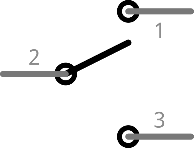
3 pins - numbered 1, 2, 3, which of those pins are S, G, V? So is pin 2 on the schematic S, or G, or V?
I just don’t know what pins of the schematic should connect to what pins in the breadboard view.
Randy
↧
Limit Switch part
While I’m not @Old_Grey, the pin id (of the form connector0pin) in breadboard needs to match a pin in schematic called connector0pin that is in the same place as the pin in breadboard and pcb. The S, G and V are likely labels on the pins in breadboard and Fritzing doesn’t care about them. It cares that connector0pin (which will be on the pin labeled S, G or V) in breadboard is in the same place connector0pin in schematic and pcb are. So in the breadboard svg, you need to figure out what connector number is associated with the pin that the S, G or V label is associated with and match that with the corresponding pin in schematic.
Peter
↧