Peter, thank you very much for your prompt response, although it is disappointing. I didn’t know there was a gerber to pdf translator either but I will try looking for one and thanks for the suggestion. I have tried to use some other PCB design tools but much happier with Fritzing so I am hoping the fixes will be included in a future upgrade.
↧
Ground Fill with gap lines
↧
Limit Switch part
Sorry wasn’t thinking, and still not 
I just buzzed them out and it looks like the 3 micro switch pins connect directly with the JST pins, so S goes to C on the switch, which I assume is common - probably your #2 -, G to NO which has no continuity when at rest but buzzes when the switch is pressed - probably #3 -, and V goes to NC which buzzes until the switch is pressed - probably #1 -.
↧
↧
Ground Fill with gap lines
Peter, Are you sure the root of the problem is not with gerber file generation? I ask because tracespace view ‘https://tracespace.io/view/’ which apparently coverts gerber to svg and it produces the same irritating lines in the svg files from gerber files produced by Fritzing. In fact, I can see the lines on the Fritzing PCB view so it may be the problem originates in the ‘Ground Fill’ function.
↧
Newbie: first circuit, thoughs?
I’ve posted the project. It’s just a test.
temperature.fzz (88.3 KB)
↧
Newbie: first circuit, thoughs?
Since the temperature sensor connectors used are all just jumpers / headers, I can not confirm that the power, ground, and data lines are being connected to the right pins when the sensors are actually attached. I can say that the connections are consistent, with the 3 lines going to the same pin of every jumper on the breadboard view.
When Initially loading the sketch file, I confirmed there is a wiring error someplace, because, on breadboard view, clicking (and holding) on one of the power or ground lines high lighted all of both the power and ground connections and breadboard rails. Fritzing sees them shorted together.
They are still shorted together after all of the wires in schematic view are deleted (Routing menu, select all traces, delete). Restoring those traces (undo), and doing the same in the pcb view also shows that power ground are shorted. Deleting all traces on both the schematic and pcb views gets rid of the short.
Hovering the mouse over the first (left) BB sensor connection shows that it is JP1. Hover over the connection point with the black wire, which is connected (through the breadboard rail) to NodeMcu GND, show that it is pin 1. Going to the schematic view and hovering the mouse of JP1, and the connection labeled one, shows that is also pin 1. Following the trace from that pin (down, right, down, right leads to NodeMCU Vin. Not ground. Same thing on pcb view. Starting from JP1, pin 1, the trace leads to Vin. Not ground.
So either both schematic and pcb have the power and ground reversed, or the breadboard view does. Without knowing which lead of the actual sensor is connected to each pin of the header, there is no way to tell which is right or wrong.
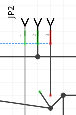
There are other problems, at least on schematic view. JP2, pin 3 is shown in red. That means it is not actually connected. The trace looks like it goes there, but it does not actually connect to the rest of the circuit. The problem is that the trace coming from pin 3 does not connect where looks like. This can be seen by moving the node where the traces appear to join, discovering what looks like another join/bend point, and attempting to move that as well. Which discovers that the 2 traces do not actually connect.
Schematic and Breadboard are inconsistent another way. On breadboard view the sensor data lines are connecting to NodeMCU pin SO. On schematic (and PCB) view, they connect to D1.
The ratsnest wires (dashed lines) on each view provide hints of these problems. A ratsnest wire is shown on a view when one of the OTHER views has an actual wire/trace between the pins that does not exist on the current view.
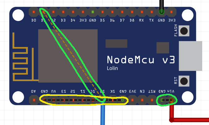
The yellow circle ratsnest above is in indication of an error in the NodeMCU part itself. The Ground pins are not connected internally.
The circled BB ratsnest above indicates another problem. Details on schematic view.

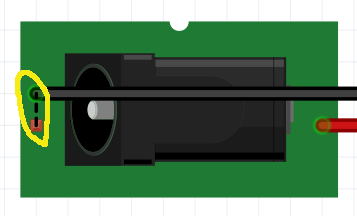
The ratsnest wire between pin 3s of JP1 and JP2 is another indication of the broken connection described above. The yellow circle on the PWR1 part shows the reason for the matching one on the BB view. There are 3 connection pins. 2 of them form a switch that is open or closed depending whether a plug is in the socket or not. On schematic view, you are connecting to the pin that is open when the power is plugged in. The ground connection should be to the bottom connection.
Going back to the initial tests, on BB view, deleting all of the wire gets rid of the power to ground shorts on the other views. As said above, need to know which sensor lead goes to which header pin to tell which is correct.
↧
↧
Limit Switch part
Yep, that is what I am trying to figure out, and thanks to @Old_Grey, I have an answer.
The part is attached to this post, but someone should run it through the parts checker script to make sure I didn’t miss anything. Anyone who runs this thru the parts checker will find errors in the PCB because there is nothing in the copper groups in the .svg file, it’s just a silkscreen. If there are any serious errors, let me know and i will fix them.
Randy
Limit Switch.fzpz (11.0 KB)
↧
Request - Arduino uno wifi Rev2
One thing that’s getting on my nerves right now is that on one side of the female headers on this Arduino Uno WiFi R2, the space between the two sets of sockets is just shy of what it needs to be to fit on a normal header in a bread board. do you know the reason for this?
↧
Request - Arduino uno wifi Rev2
If you mean the two header strips are separated by a hole and a half instead of a two holes, then that’s just how Arduino made them - their whole lineup is like that -. Yeah it’s annoying.
↧
Newbie: first circuit, thoughs?
Thank you for the deep review, greatly apreciated.
I did some changes:
temperature.fzz (91.8 KB)
One issue i had is to properly “detect” the 3.5mm jack orientation on PCB, the part i’ve used, are shown revesed in any online store, so I had to reverse the whole design. Why Fritzing is showing the part upside-down ?
When the design is ok, i would like to improve by using SMD components and, if possible, make a BOM list to provide to an online fab to get a simple PCB with all components (presoldered, if possible).
It’s just a test, but let’s do this step by step.
Another question: fritzing is saying the a line crossing the resistor, is broken. That’s true, because the resistor must close the circuit. Why fritzing is complaining about this ? Doens’t detect the resistor ?
The wiring on the sensor cable is not important, i have to solder the jack plug on my own so i’ll do based on my design. What I would like to is to keep the gnd and sleeve connected together (i’m using parasite mode) even in the cable, so the only real pin is the left one that has to go to D5 on NodeMCU. The other two are joined together
↧
↧
Newbie: first circuit, thoughs?

↧
Newbie: first circuit, thoughs?
In BB view pin 1 is on the NodeMcu side, and in SCH pin 0 of the resistor is on NodeMcu. Just flip it around in SCH.
↧
Newbie: first circuit, thoughs?
I’ve flipped the resistor in schema view, now fritzing is happy 
↧
Newbie: first circuit, thoughs?
Not that it matters, but there is a link missing between the pins on the DC jack in BB view.
I think you have to move the 3.5 audio’s to the edge or it might be hard to plug them in.
Before getting this made make sure you print the PCB on paper and that the parts fit on it. I would even gerber check it.
↧
↧
Newbie: first circuit, thoughs?

↧
Newbie: first circuit, thoughs?
R1 is supposed to be a “PULLUP” resistor. That is, D5 should connect directly to the sensor data lines, and the resistor goes from that line to power. Since the NodeMCU is a 3.3 device, “power” is also 3.3V. See “Powering the DS18B20” on page 5 of the datasheet and have a close look at the associated figure 6. For your purposes, Vpu in that is the 3.3V that NodeMCU runs at, not the 5V at Vin. As long as the data pin can “source” 1.5mA, the added switch to power during temperature conversions is not needed.
Here is my take on the sketch document.
temperature.fzz (37.3 KB)
Fritzing is going to show the power jack however the part has been defined. That part is from sparkfun, and will have been designed to match their part. I do not know what you mean by “upside down” it looks correct to me, compared to the breakout board image and connectors in breadboard view. Power on the end, with the ground and gndbreak pin in middle and edge, and the open end pointed away, which would be off board so the plug will fit.
If you mean it was rotated 180 degrees on pcb view when initially placed, that is somewhat random. Fritzing does not have any information about which way it should be oriented. There is no intent to force the different views to be lined up the same way. Just because the power jack is on the left, facing left, in breadboard view does not mean it will be the same on the pcb.
↧
Request - Arduino uno wifi Rev2
But…why??? OMG it’s SOOO irritating! If i knew there was a good reason, i would feel less annoyed by it.  I’m curious if anyone knows.
↧
Part breadboard with gradient
hi, ok vanepp thanks for replying …
I’m going to start modifying all the svg and I’m going to create the parts manually.
I will also remove the Pcb and Schematic views as they are not necessary.
I didn’t rename the connectors in inkscape because I saw that creating the parts with the editor generates it by itself. But from what you clarified for me above it is necessary to simplify fritzing.
Thank you all for your time.
↧
↧
Change Hole Size
I had a PCB made that I designed using Fritzing. The hole sizes for standard through hole resistors and TO92 transistors are huge. For version 2 of my board, I would like to shrink the hole sized on these parts to 0.7mm, but I dont know how?? My resistor is pin spacing is 300mill.

↧
Help! My optocoupler circuit hates my Capacitor!
Please refer to my previous post. In a nutshell:
The circuit is supplied by a 15v ac dcc voltage which has both a power and digital command component.
My circuit is effective a 5v dc supply in parallel with an optocoupler circuit; the circuit I used is shown in the link above.
My circuit consists of ac in at J2 J4 Bridge rectifier to a 5v volatge regulator at IC2 for a 5v supply for the lighting and the digispark. In parallel with the optocoupler circuit. The optocoupler circuit requires 5v derived from the 5v dc supply. The optocoupler circuit sends a logic signal to Pin 2 of the digispark and the lighting is controlled via pins 1,3,4 and 5. I have shown tracks to holes in the board so that on the other side of the board I can solder sections of 5v LED self adhesive strip which can be independently controlled at J6,J7,J8,J9 with J10, J11,J12,J13 as ground.
I have also left holes at J1 and J5 in order to add a capacitor to provide a"stay alive" function for the dc supply. Since the capacitor is massive compared to the other parts I intend to solder flying leads to J1 and J5 and hide the cap somewhere in the body of the coach. As it is the components fit into the roof curve without too much difficulty.
Using the input from Micro Merlin (Thanks for the input) I revised the board and had some samples made, fully expecting to have to correct my mistakes. Mistakes were: Bridge rectifier around the wrong way,missed out a resistor, missed out a track from the optocoupler to the Attiny85. Despite this, once I rectified these errors on the sample boards it works!!! Lights go on and off from a dcc controller and when placed in a coach and pick up from the track lights go on and off. Job done I thought. I have modified the board to rectify my errors and the latest version is below. I have spaced things out to allow for components to be bent over to allow for a very small headroom. I also discovered that the ATTiny 85 Micro USB has a different footprint to the ATTiny 85 USB, the row of pins is 0.1" closer on the Micro USB so to allow for using both I added an extra header
There is now a problem which I cannot fathom! Everything works right up until the time I add a capcitor at C1. Then no response from the dcc circuit lights do not turn on or off. remove the capacitor from the circuit and everything works fine.
So far I have tried:
separating the input feed----same outcome
removing the track between the voltage rectifier and R3 connecting it directly to the digispark— same outcome
removing the link between C1 and the Opto connecting the opto to GND on the digspark— same outcome
a combination of all of the above----same outcome
Sa5v supply to digispark3H.fzz (43.9 KB) me thing happens all works fine until Capacitor added at C1 then no response form the dcc,
assisting it with 2.5lb lump hammer–different outcome same result!
Does anyone have any insight into what is happening. I cannot see what difference the Capacitor would have. It is there to provide a stay alive function for the regulator otherwise the lights will flicker. I do not see how it can be interfering with the dcc signal but clearly it is. Can anyone suggest a work around. Even better does anyone understand what is going on!?
Thanks for any suggestions
5v supply to digispark3H.fzz (43.9 KB)
↧
MicroSD_Badusb Arduino Leonardo
Hello,
Do you know if that is possible to use ds18b20 temperature sensor with this board please ?
Thanks
↧