Thank you for that. We RC hobbiests call this “servo”. But, yes it’s a motor. I guess I need to make one myself . But the view would be like from my screenshot. I found that in a Fritzing picture, so I though they exist.
Thanks again.
Servo connector (male and female)
Servo connector (male and female)
There is a servo in core parts (with three wires unlike the motor above which only has two.)
It is configured with bendable wires so you can extend the wire as I have done with the signal wire. It should (I haven’t done it) be possible to make a more header like end to the wire, but only for each wire there is no facility to group wires together. So it would end up as three single pin headers each needing to be placed on the receiving connector in the correct order instead of a three pin header. By left mouse clicking the wire and holding down the cntrl key you can cause the wires to bend like this

which is the main advantage of the bendable leg parts along with being able to change the length of the wire in a sketch. Bendable leg parts are fairly difficult to make (I don’t remember if I included that in my tutorial series) so you may be better off to get me to make a part for you if this is what you need.
Peter
Program DO-201 Is it on the?
I do not understand exactly everything you are explaining to me, I changed the connection of the transistor because it worked but indeed it was connected backwards.
I did some test with the base of the transistor and 1k ohm is already preventing operation.
I’m sorry I’m taking a long time because my health prevents me from concentrating at the moment (nothing serious, just binding ^^)
By copying onto a breadboard what I did on the components view, there is no problem. So I don’t quite understand. The 5v passes through the 2n2222 then puts the relay coil under tension with the GND on the other side. I put a diode as you had advised to avoid the return of the coil when it goes to OFF so why remove it now?
Yes I have to put a Maasedqais resistance of how many ohms so that it does not go below 12v?
I am really sorry for my dificulties in understanding between my lack of knowledge and the approximative translation problems of our friend google ^^
Here is where I am.Nouveau routage 5.fzz (76.8 KB)
I need voice recognition module part
i need voice recognition module part
Mini-360 DC-DC Buck converter
i need voice recognition module please
I need voice recognition module part
To find or make a suitable part we would need the spec sheet (connections and mechanical drawing preferred) of the voice recognition module you want to use.
Peter
Program DO-201 Is it on the?
Nothing to be sorry for, reply when ever you can, I’m not in any hurry. The important part is for us to get something that will work for you!
It will indeed work as an emitter follower (which is what you have now) but a 1k resistor should give about 5ma of base current which should switch up to 1A or more at the emitter, so the relay should work with a 1K base resistor. The diode needs to go across the coil not in series with the coil. Here I have made the necessary changes in both schematic and pcb to produce a correct configuration.
I rotated the power connector by 180 degrees so it matches the orientation in pcb (input power at the top and gound at the bottom.) The diode is across the coil as it needs to be, I added a value (12 ohms will limit the charge current to about 1A) to R6 and moved the connection on J12 to pin 2 (as pin2 and pin3 are connected together on the capacitor board which will cause a loop which is undesirable.) Here is a copy of the complete sketch:
Nouveau routage 5-3.fzz (78.1 KB)
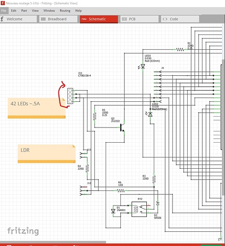
As I understand it there are 42 LEDs connected between pin 1 and pin 2 of J11. Assuming 10ma per LED that would need .42A to power them. R4 at 220ohms and the LDR on J13 won’t let 0.42A flow to the LEDs so I expect I am misunderstanding something here.
This appears to be a problem with translation. As it stands it doesn’t make any sense to me. Which resistor in the drawing are you interested in the value of?
Peter
How to resolve electronic mail related issues faced Att.net?
Hi!
We offer help for the entirety of the difficulties related to Att net . We were supporting our clients dealing with any electronic mail related issues. We have a gathering of experts who offer short and green strategy to our clients. In the event that you are endeavoring to login to Att net, anyway couldn’t achieve that due to any issue, at that point name us at our help number.
Set picture on surface of pcb
hi at all,
I’ve following problem: I tried to set a picture/logo on the surface of the pcp. I’ve used the “silkscreen image” tool in the core parts. I changed the picture file but I only get vertical stripes. I already tried zu reduce my picture size or file type - but it don’t work.
Did anyone have an solution or have/had the same problem?
Best regards
Christian
Water pump/motor part here!

HELLO,I SEARCH FOR THİS PART BUT I CAN FİND,SO I MAKE IT .GOOD FRİTZİNGS  WATER PUMP.fzpz (6.8 KB)
DS1307 arduino help pls
okay i get it now, thanks a lot anyway.
Cheers
Servo connector (male and female)
Thank you. I’ll have a look at that as well.
Andreas
Water pump/motor part here!
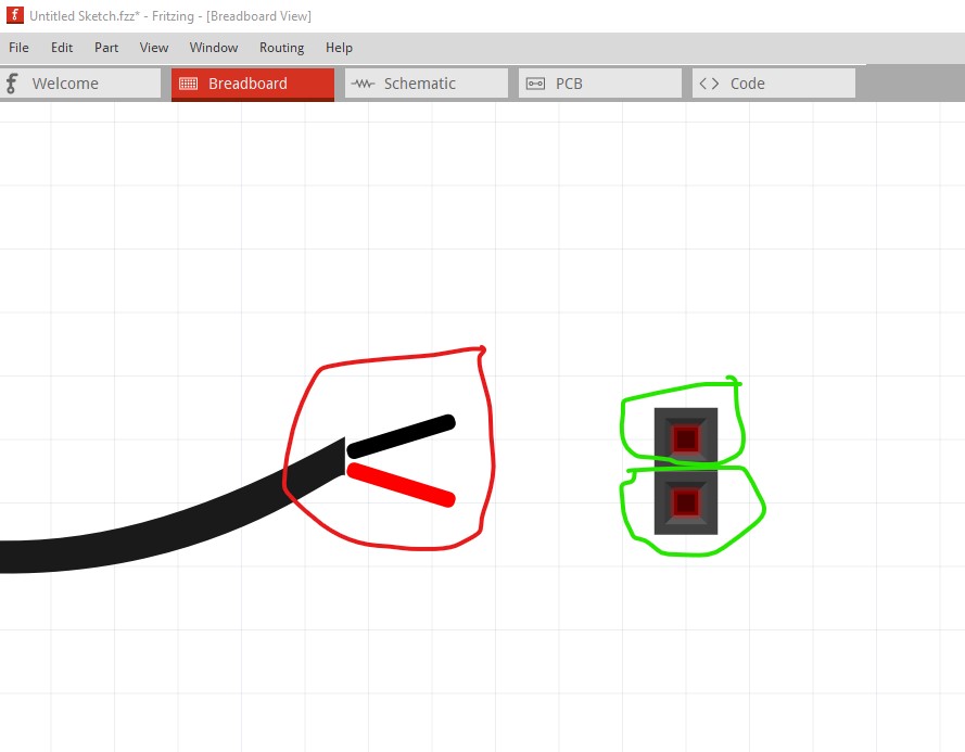
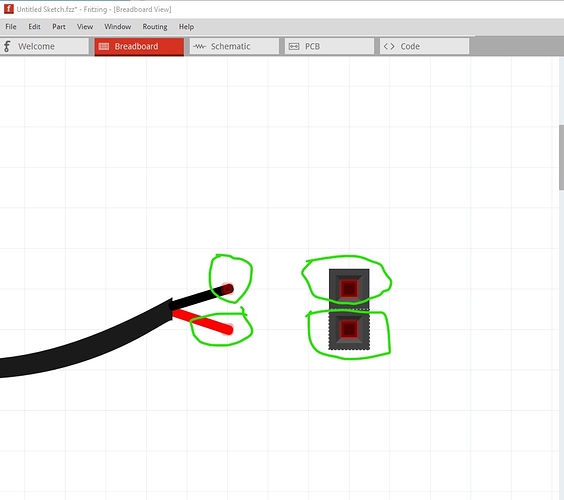
Not a bad job, but again a few problems. Breadboard lacks a layerId, and is dimensioned in px (although the scale is correct in both Fritzing and Inkscape despite that.) The motor part you cloned from is a bendable leg part and this one is not correctly configured for bendable legs so breadboard doesn’t work. This is your part in breadboard with a two pin connector beside it. Note the red squares in the header connector (which indicate active but unconnected connections.) Your part does not have such connections on the pins and thus won’t connect.
As before I ran your part through FritzingCheckPart.py and it generated these complaints (along with some more that are ignorable):
Warning 19: File
‘svg.breadboard.prefix0000_ad48e12d475048711e5902646654db99_6_breadboard.svg.bak’
At line 2
Height 114.22708892822266px is defined in px
in or mm is a better option (px can cause scaling problems!)
Warning 19: File
‘svg.breadboard.prefix0000_ad48e12d475048711e5902646654db99_6_breadboard.svg.bak’
At line 2
Width 337.2832336425781px is defined in px
in or mm is a better option (px can cause scaling problems!)
Error 69: File
‘svg.breadboard.prefix0000_ad48e12d475048711e5902646654db99_6_breadboard.svg.bak’
At line 9
Found a drawing element before a layerId (or no layerId)
Error 18: File
‘part.prefix0000_ad48e12d475048711e5902646654db99_4.fzp.bak’
Connector connector0leg is in the fzp file but not the svg file. (typo?)
svg svg.breadboard.prefix0000_ad48e12d475048711e5902646654db99_6_breadboard.svg.bak
Error 18: File
‘part.prefix0000_ad48e12d475048711e5902646654db99_4.fzp.bak’
Connector connector1leg is in the fzp file but not the svg file. (typo?)
svg svg.breadboard.prefix0000_ad48e12d475048711e5902646654db99_6_breadboard.svg.bak
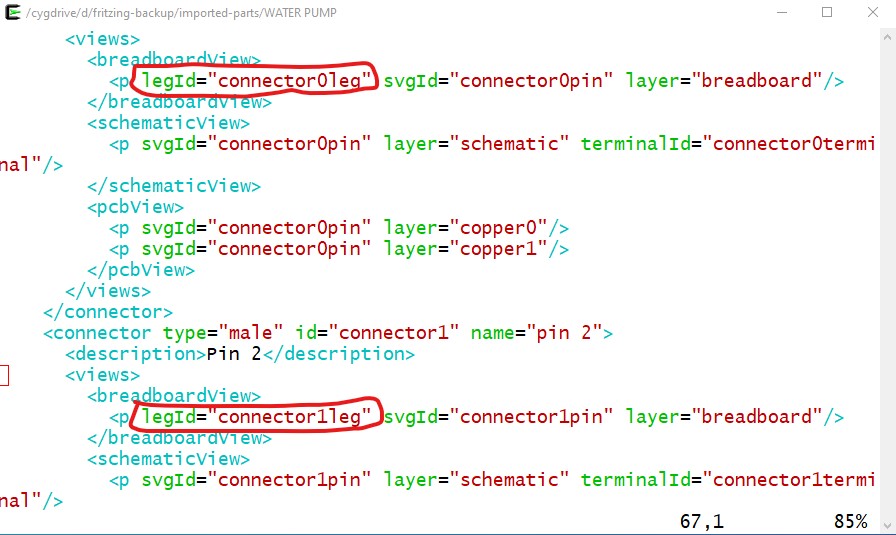
The last two are the indication that this was a bendable leg part to start with. To correct that you need to edit the
part.prefix0000_ad48e12d475048711e5902646654db99_4.fzp
with a text editor and remove the two legId statements (circled in red here):
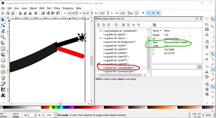
Then you need to add proper pins to the breadboard svg like this:
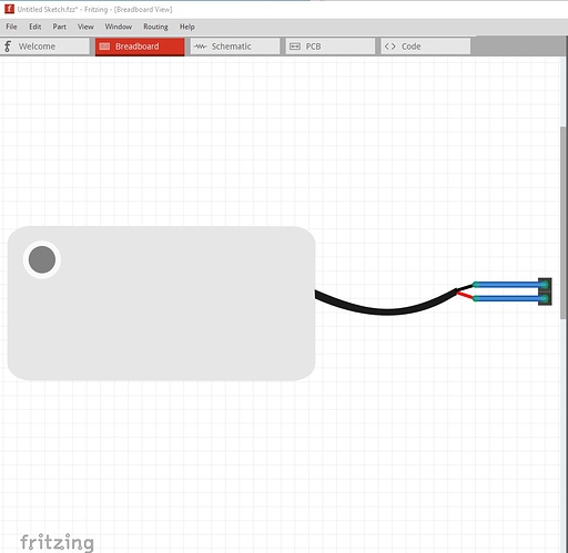
Here I created an invisible (fill:none stroke:none) rectangle the same size as the wire and positioned it on the tip of the wire. Then I duplicated it and moved it down .1in in y to make the other pin below it and skewed the red and black wires til they align with the new pins. Then I did an Edit->Select All, an Edit =->Resize page to selection, an Object->group then renamed the group to breadboard to create the layerId and recreated the part. Now in breadboard the pump has connectors which will connect to the two pin header and make the connection:
Note the faint red square on the end of the wires indicating a connection.
Now when I make the connections in breadboard:
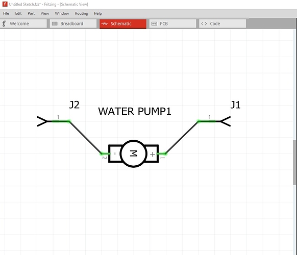
they reflect in to schematic and pcb as they should
Unlike your original part in the first image in this post which won’t connect in breadboard. Here is the fixed part:
WATER PUMP-fixed.fzpz (7.3 KB)
Peter
Modify 8x8 matrix
I would need a 32x32mm MAX7219 8x8 LED Matrix part that is using SPI. This is the actual module: https://robotdyn.com/matrix-led-8x8-module-32x32mm-driver-max7219-7221.html
I found the attached part, which is almost perfect, except for the spacing of the pins.
MAX7219 LedMatrix Red Module-fixed.fzpz (8.0 KB)
My module spans a whole breadboard vertically with a one row gap. I don’t know how to describe it better but here’s a picture (red squares would be the pins)
Could somebody please help me modify that part by reducing the width of these pins? I tried the parts editor but I can’t move anything. Thank you 
Modify 8x8 matrix
Modify 8x8 matrix
Hi Peter,
wow, this is perfect, thank you so much! You even caught the incorrect pin order which for some reason I missed. You just saved me from having to throw away 5 PCBs (or mess around with flying wires). And it also looks like a 8x8 LED matrix now.
I actually think this is the most common size. I compared it to an old 2*5 pin I2C matrix I have lying around and it has the same pin spacing and dimensions.
The only thing I would change is the naming of the SDI/SDO pins. You named SDO as SDI Out but SD stands for Serial Data so it’s Serial Data In (SDI) and Serial Data Out (SDO).
I would have changed it myself but I see that it’s in the SVG files and I have nothing to edit them.
Thank you again for your quick help with this!
~ Alex
Modify 8x8 matrix
You are right, old eyes. I missed that only the other 4 pins are connected together not SDI/SDO in the schematic. It should have been obvious when I needed to add a bus entry for the SDI pins but it wasn’t. It would also be a good bet to make sure the pins are in the correct order looking down from the top because I had to mentally rotate the bottom of the board image on the web site by 90 degrees then invert it to get to the top of the board and I may not have done it right (although I think it is!) I have replaced the part above with a corrected one. You will need to delete the part in your mine parts bin then restart Fritzing to get it to really be deleted.
The usual answer is Inkscape (which is open source) but it is fairly complex to use. Various of the commercial packages (Illustrator, Coral Draw others for the Mac) work as well but Inkscape is the most familiar one usually. As well in this case you would need to change the bus configuration (internal connections in the parts editor) to remove the link I added from SDI to SDO. Someone in a recent thread has found an online svg editor, but it seems to be like Illustrator and shield you from some of the important parts (such as dimensioning the drawing in px which causes scaling issues in Fritzing. ) Inkscape used to be poorly supported on the Mac (I think for a while they didn’t publish Mac versions) but I think that may have changed now with the latest version, but I’m not a Mac user.
Peter
USB to CAN converter
Hello, i’m looking for a USB to CAN converter part like this:

How canva resi̇ze i̇n inkspace?
Hello,How I can resize the canva in the İnkspace ?
How canva resi̇ze i̇n inkspace?
I’m not sure I understand the question. You can draw as large as you want by default, when you are done you need to do Edit->Select All then Edit->Resize page to selection. That will resize the view box to the elements of the drawing and reset the starting point to 0 0.
Peter

