↧
Part help usb micro usb


↧
Part help usb micro usb
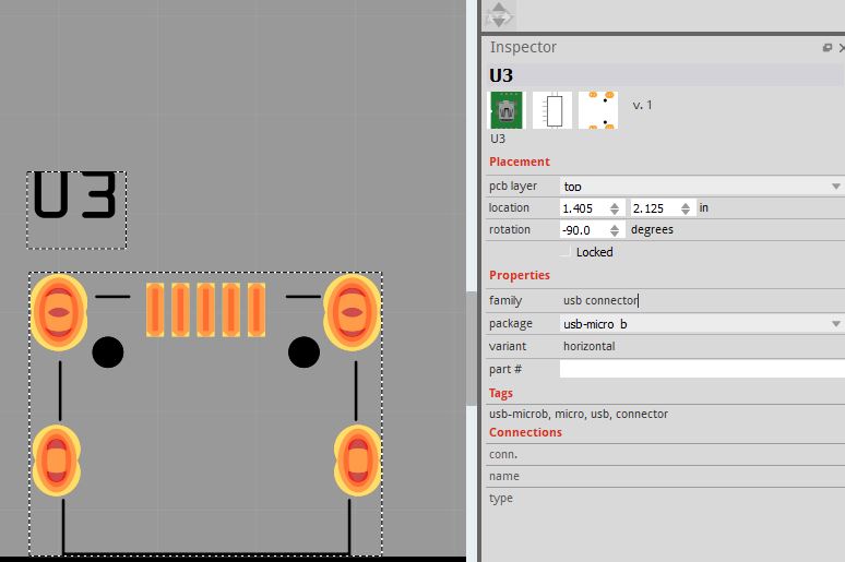
Presumably the part this was made from had pins that yours doesn’t although they aren’t holes but marks where you could drag a hole in the sketch on to the board if you needed them (and don’t appear to be working as they don’t appear on silkscreen here!)

the thing of importance is to check the size of the drill holes (circled in red in the image which is the gerber output of the usb connector) that are being used to simulate the slots for the tabs (Fritzing and many board houses doesn’t do slots in general.) You need to check the size of the mounting pins and make sure they will fit in these holes (from the drill.txt file in the gerber output)
; NON-PLATED HOLES START AT T1
; THROUGH (PLATED) HOLES START AT T100
M48
INCH
T1C0.043889
T2C0.034306
T3C0.031500
T100C0.038000
%
T1
X024821Y013281
X024821Y016250
X024621Y013281
X024621Y016250
T2
X023103Y013222
X023340Y016273
X023340Y013222
X023103Y016273
T3
X024318Y013769
X024318Y015752
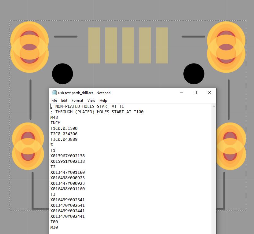
drill sizes are in inches so T1C0.043889 indicates a 0.43889in hole for the T1 holes. You need to make sure the tabs on your connector will fit in a hole of that size (or be prepared to file it out more, or modify the part if it won’t.) Printing out the footprint at 1:1 scale and checking it against a real part for positioning is also a good bet as the part is generic and may not match your particular connector.
Peter
↧
↧
Part help usb micro usb
thanks Peter,
so I get the values in the drill text file as follows:
but it’s not clear to me which holes are which - I measured the connector so it has two different pin sizes: 2 at front: 0.0335 & 2 at back 0.0305. T2 & T3 resp? T3 the black holes? Aslo the pins are rectangular so it seems this is achieved by two holes sideby side?
I also zoomed in close on the pcb layout and compared the X/Y cordinates bottom right hands side and the pin distances match up pretty ok with the physicalpart.
↧
Part help usb micro usb
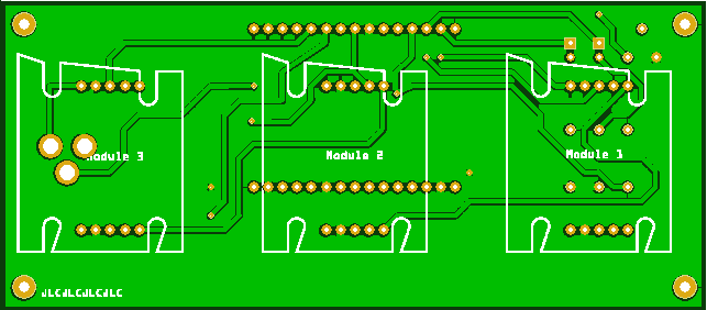
The T1 number indicates which set of drill X/Y coord will be that size, so you need to move to that coord in the gerber viewer (this is gerbv) to tell where the hole is:

here I chose the t1 holes then the first hole and moved the cursor in the drawing to the listed coordinates which tells me that it is the front hole of the bottom front pair (circled in red) that are 0.043889in and the two back holes are 0.03406in the orange pins (no copper around them which is why orange) are 0.0315, presumably you can ignore those as you don’t need them but they shouldn’t hurt anything as long as you don’t run a trace there.
Yes, Fritzing supports cutting slots poorly  and most of the cheap board houses don’t do rectangular slots so typically overlapping holes are used to make slots. I haven’t tried this but folks that have say it works fine.
Peter
↧
USB to CAN converter
This should do what you want. There is no pcb view as it isn’t useful. There are no USB connections (although the connector is present.) Someone made some cables (with no connectors) for the Raspberry PI parts a while ago, they should be in the forum somewhere.
inno-USB-CAN-module.fzpz (16.1 KB)
Peter
↧
↧
Unable to add silkscreen image
I’m using Fritzing Version 0.9.4 on macOS and I’m trying to place an SVG image on the silkscreen layer of my PCB. I’m fairly sure this exact image worked in the past but weirdly enough I can’t get it to place ANY SVG or PNG image now.
Every image fails with “Unable to load due to rendering error”:

The image I’m trying to place is extremely simple:

↧
Modify 8x8 matrix
Oh no you did a perfect job in such a short amount of time! It’s clear that you are an expert. Thank you again and thank you for fixing the part.
The pins are in the correct order. I just printed the board on a piece of paper and verified all the traces.
I noticed one tiny last thing: in the PCB view, the connection is still called SDI-out. But that is just a label issue.
Inkscape seems to work juse fine! The UI is more Windows-like but I think I might be able to fix some small things
↧
Modify 8x8 matrix

↧
Modify 8x8 matrix

↧
↧
Modify 8x8 matrix
Yes, I fixed all the svgs but missed the name field in the fzp file. I just replaced the part yet again with a corrected version.
Peter
↧
Unable to add silkscreen image
That SVG image does not have any physical dimensions. Fritzing requires that to be able to scale the image to match the reset of the PCB graphics. To get it to work, I changed the svg header from:
<svg xmlns:dc="http://purl.org/dc/elements/1.1/" xmlns:cc="http://creativecommons.org/ns#" xmlns:rdf="http://www.w3.org/1999/02/22-rdf-syntax-ns#" xmlns:svg="http://www.w3.org/2000/svg" xmlns="http://www.w3.org/2000/svg" version="1.1" x="0px" y="0px" viewBox="0 0 1000 1000" enable-background="new 0 0 1000 1000" xml:space="preserve">
to
<svg xmlns:dc="http://purl.org/dc/elements/1.1/" xmlns:cc="http://creativecommons.org/ns#" xmlns:rdf="http://www.w3.org/1999/02/22-rdf-syntax-ns#" xmlns:svg="http://www.w3.org/2000/svg" xmlns="http://www.w3.org/2000/svg" version="1.1" x="0px" y="0px" width="1in" height="1in" viewBox="0 0 1000 1000" enable-background="new 0 0 1000 1000" xml:space="preserve">
or, excluding most of the properties, from
<svg x="0px" y="0px" viewBox="0 0 1000 1000" >
to
<svg x="0px" y="0px" width="1in" height="1in" viewBox="0 0 1000 1000" >
The 1 inch references were arbitrary. I do not know what size the graphic is supposed to be. 1 inch means that the “1000 1000” viewbox values come out to mils.
I do not see any clues in the svg file about what tool was used to create it. Any that I know about would have included some sort of length and width values, even if they were in pixels. Pixels are not good, because translation from that to real world units is not consistent.
↧
Unable to add silkscreen image
Thanks! You are right, that worked.
The file was made with Illustrator but I also copied it and saved it from Inkscape, after the original Illustrator file didn’t work.
When that didn’t work either, I started stripping out properties, thinking that one of them was maybe messing up the rendering.
Weirdly, Apple Preview, Illustrator and Inkscape all open that file just fine, and so does my browser. Only Fritzing didn’t want to play nicely.
What’s more weird is that exporting it as a PNG also didn’t work in Fritzing.
Either way, thank you for your expertise! I could import the file with your modifications!
↧
Unable to add silkscreen image
Fritzing is the only one that needs to know real world dimensions. To render the image, it MUST scale it to match the units used for the pcb view. The rest can safely make assumptions without worrying about accuracy. They do not care whether the drawing represents 1mm, 1in, 1mile 100km. Fritzing does care.
↧
↧
Modify 8x8 matrix
Thank you so much Peter. Third time’s the charm!
And you are right, works just fine on 0.9.6 (though now there are some new bugs, but not with this part). For some reason I was still on 0.9.4.
I noticed that the donation on download is now mandatory (ish). I hope that gets the project some well deserved money!
↧
Modify 8x8 matrix
We are all hoping that , the voluntary donation rate was something like 0.1% of downloads. While the paywall is very unpopular, it is necessary if Fritzing is to survive. The way forward is thought to be paid professional developers, the code base is too complex for volunteers. I tried to restart development for about 3 years with 0 success. Lots of people arguing for a fork of the code base, but none willing or able to actually produce pull requests on the current code base, where the maintainers said they would merge valid pull requests, there just weren’t any. The paywall (and Aisler, whose CTO drove the push that got 0.9.4 released!) have produced (mostly invisible) updates to the web site, forum and build chain (all a huge amount of work!) and the 0.9.4 and 0.9.6 releases at a time when Fritzing was starting to die from outdated libraries.
Peter
↧
Unable to add silkscreen image
I hadn’t thought to look at the header lines. I had discovered the path loaded when added to the Fritzing icon.svg in core parts, but your answer came before I got further than that .
Peter
↧
Unable to add silkscreen image
Most of the online SVG compressors/optimizers seem to strip out the physical dimensions.
I just noticed with 0.9.6 that the physical dimensions in the SVG override whatever is set in Fritzing, and transformations also don’t seem to get applied – strange bug. The gerber files I produced with your fixed SVG suddenly showed a HUGE icon. But that was easily fixed
↧
↧
Modify 8x8 matrix
I can see that this would make sense. Being a developer myself (well now more operations, but still) and having worked with large code bases, I can imagine that this isn’t something you could maintain with only volunteers. 0.1% donation rate also doesn’t really shock me.
It’s a great tool for the occasional DIY PCB that I do. I’m not an electrical engineer but I made a large 35x35cm PCB with Eagle once and that gave me a fair share of gray hair.
↧
Unable to add silkscreen image
In general gerber processing (which happens after pcbview is rendered) doesn’t do transforms. So it is possible to have something that looks fine in pcbview but isn’t fine in the gerber output, which is why I usually check the geber output is correct. A bunch of the bugs have been fixed in 0.9.6 and there is at least one more that is now fixed in 0.9.7 when it gets released. One common one is that stroke-width that is optimized in to a higher level group (and inherits properly in Fritzing but not gerber processing) causes the pads to not have holes. FritzingCheckPart.py manually (or at least is supposed to, I think there may be a bug there when I was looking at the code) inherits the stroke-width value to fix that. It is also true that bendable legs (at least, there may be more cases) doesn’t deal with the CSS style attribute, so FritzingCheckPart.py also inlines all the style commands. Fritzing also doesn’t like px in font-sizes (parts editor changes the font-size to 0 causing the text to disappear) so that gets fixed too.
Peter
Peter
↧
Modify 8x8 matrix
That and breadboard view (which is unique AFAIK in open source at least) are Fritzing’s strengths. It is relatively easy to use (although parts making is not) and is the only open source package I know of that will allow you to document the connection of a series of modules (as long as there are parts for them) which is mostly what I do these days rather than make boards. It is very popular in the maker community (around 200,000 users from github parts update statistics I believe.) Unfortunately the developer class folks find it too limiting and move on to kicad, Eagle or one of the commercial offerings.
Peter
↧