Yes, that's what happens.
I've been making double row headers in SCH for past week because they are more compact.
Yes, that's what happens.
I've been making double row headers in SCH for past week because they are more compact.
I've been doing a large SMD project and I noticed that there is a very big problem that is probably going to need a global solution.
Basically the halo around ratsnests/wires that enable you to click on them is so large, that it makes it impossible to pick up SMD parts that are tightly packed and connected. There is one way to get around it, by clicking the part in SCH and then going back to PCB and changing location in Inspector, but this is slow and clunky and not equal to the convenience of other EDAs.
Since we can't change the Fritzing program, I've come up with an idea that we all need to implement from now on that might patch up the problem enough that it will nearly be as good as other EDAs. The idea is to use bigger page sizes than the minimum so that there is overhang to grab on to. A tab out the side and top seams good, or maybe a 0.010" boarder, but that may render the top and bottom unclickable in tight packs.
What do you think?
I have some workarounds for you.
You can turn off ratsnest view while moving the components. Although sometimes this can make knowing where to put them harder.
Sometimes you can right click a component that is impossible to left click.You can then move the part using the input fields in the inspector.
Sometimes you can get it to select them by holding down ctrl as if you were selecting multiple.
You can select another component or the PCB first and then use ctrl to select the one you want and then de-select the first component. This seems to prevent Fritzing from selecting ratsnets because you can't select components and ratsnets in the same grab.
Yay, the turn off ratsnest worked - 2 years and I didn't notice that -.
I used your method of selecting in a different view for a while until I came across one of the other methods and then realizing you could make them hidden was even better. What we need is keyboard shortcuts to toggle the views and it would be perfect.
I got the "select part in another view" from someone else as well, and I had played with those turn-off view once before, but it didn't occur to me to turn off the ratsnest.
Last night it was getting me down when I could pickup a part easily because I have about 30 parts to move.
My beginners luck has just failed. I have created a shaped pcb board in Inkscape. I have the main board on layer "Board". filled but no Stroke. Then on layer "Silkscreen" I have the same shape but no fill and Stroke set. The page is set to the same size as the objects. I then checked the XML data and I have the id's set to Board and Silkscreen. It loads into Fritzing as a custom shape, but error messages come up saying there is no Silkscreen layer. There is. So I press OK to use the board anyway. Then another box about cutouts. OK to that too. The board comes up on screen as normal.
So I then try to export to OshPark and I get an error to say:
Removed empty file "iSpindle V6.1/ispindle v6_pcb1_18490250_contour.gm1".
I can't find a board outline file.
The XML data is below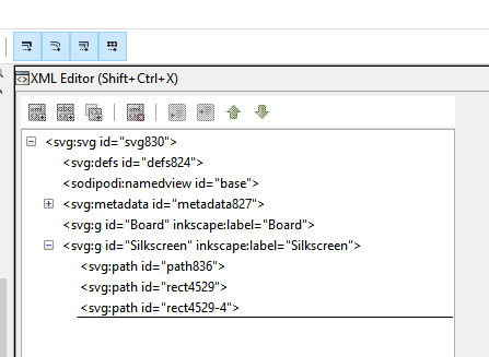
Ay ideas why it isn't loading properly?
If you could upload the SVG I would be happy to have a look.
If your board does have holes in it look at tip number 3 http://forum.fritzing.org/t/inkscape-tips-and-tricks/4192
Last thing that may or may not have any effect is I have always used lower case names silkscreen not Silkscreen. I can not say it is an issue but it was the first thing I noticed when I read your post.
Not sure that the forum uploaded the svg file. so posted it on Sabercat just in case.
You have two groups:
Board which should contain the board as a solid in green. But in your case it was blank.
In your silkscreen you have three paths.
path836
rect4529
rect4529-4
path836 is a slightly smaller version of the next paths and should be deleted (I think).
rect4529 looks to be a solid green board layer which is your missing board layer.
rect4529-4 is the silkscreen outline you want in this layer. (I no longer use a silkscreen on my board outline as it tends to never line up perfectly with the milling).
So i have moved rect4529 out of the silkscreen and into the board group and renamed it board not Board. I then deleted path836 from the silkscreen group.
That still resulted in the complaint of no silkscreen layer and as I suspected it wanted silkscreen not Silkscreen. Right click and save as.
Also I should say if you have not found the xml editor in inkscape yet press (Shift Crtl X) to bring it up.
Many thanks. I see you have changed it to lower case silkscreen. I did wonder why in xml it looked like all the objects seemed to be on one layer. When editing I thought I moved the green board layer to the board and the other to the silkscreen. I'll upload version and give it a go. Thanks for your help.
I am still battling with my PCB Layout and using Linux.
I did not use the Breadboard view when starting my circuit layout.
The pcb was designed entirely using the PCB view.
Not being able to change some of the component connections to the bottom copper layer I did a design rules check and it seems that everything (Both the Tracks & Components) are all on the bottom copper Layer, How Can I move all the components to the top layer leaving the tracks on the bottom layer?
PCB view only is fine - I don't use BB -.
Upload the file with the 7th button above.
And the best news yet. It worked in OshPark.  Many thanks for your help.
I made a part based in a Ard Mega, and now when I click on some pins in SCH other pins light up yellow like they are connected.
How do you disconnect internal links?
Have you checked in the editor? Under the list of pins on the right there is a check box that says set internal connections. Once checked it will show any internal connections as ratsnests. You can then right click on those and delete them.
I remember seeing it just couldn't remember where, either that or 6hr of part making got to me,
Never used it before, quite interesting how it works.
I replaced the the uploaded parts with actual ones. I found a wrong connection in the PCB and fixed it.


