Quantcast
Channel: fritzing forum - Latest posts
Viewing all 31021 articles
Browse latest View live

Mega2560 R3 Pro Mini

$
0
0

I can't find any useful information about the Mega2560 R3 Pro Mini, no datasheet no info no explanation of pinouts, and I don't have a sample to check. This was made entirely from online photos and guess work, so you need to throughly check it before production because I can't verify it's accuracy.

From photos it looks like a compact version of the official Arduino Mega2560, with it's better Atmega16U2 chip, but the DC power supply has been removed. Other photos show it plugs into prefboard, so I assume it's 21 x 15 pins on a 0.100" pitch.

All available info - https://www.google.com.au/search?client=opera&q=Meduino+Mega2560&sourceid=opera&ie=UTF-8&oe=UTF-8

Introduction:
This Meduino Mega2560 Pro Mini board is a small version of the Mega2560 board. It's completely compatible with the original Arduino Mega2560. For the original Mega2560 it has a big board size, some time it maybe not easy to embed it into your system, the Meduino Mega2560 Pro Mini board will be more easy for embedding it into your system. It's cute and small size.

Features:
Completely compatible with original Arduino Mega2560
Pin pitch: 0.1 inch
Size: 5.42cm*3.68cm
With Atmega16U2 chip as the USB to Serial converter
5V working voltage.
Input Voltage:7-12V
Analog Input Pins: 16
Digital I/O pins: 54

V1.0 - Mega2560 R3 Pro Mini - Mega2560 R3 Pro Mini.fzpz (44.9 KB)

There are versions without headers, but this the version with female headers attached to the underside.


Information about projects

$
0
0

Try as I might I cannot find any notes accompanying projects. I see all the projects from beginner to advanced. How do I read information about them?

How to change all Part Connections to Bottom layer?

How to change all Part Connections to Bottom layer?

$
0
0

Not sure how to send the PCB .


PCB2


How to change all Part Connections to Bottom layer?

How to change all Part Connections to Bottom layer?

$
0
0

Get the sketch .fzz, press the 7th button above when you reply, and enter it there.

How to change all Part Connections to Bottom layer?

How to change all Part Connections to Bottom layer?

$
0
0

Nope, didn't upload. The forum usually doesn't like svg files (it will try and render them, and often fails) so its easiest to upload either an fzpz part file or an fzz sketch file (both of which upload correctly). The 7th icon from the left on the reply menu in the forum is the upload key (a bar with an arrow pointing up). That should open a file dialog box that lets you select the file to upload. If you want to upload a svg file, rename it from .svg to .fzpz and upload the fzpz file then tell us it is really an svg.

Peter


Information about projects

$
0
0

Often there aren't any notes with a project just the fzz sketch file for the project. If the project looks interesting down load the fzz file and load it in to fritzing to look at it.

Peter

Information about projects

I need to build a circuit like this on the Breadboard of Fritzing... Can someone help?

$
0
0

I'm completely new to this software and i don't know nothing of it. Can someone build it on the breadboard and explain me why it is like that ?

And i know this may be something very easy but if you could help me i would really appreciate ! Thanks guys !

I need to build a circuit like this on the Breadboard of Fritzing... Can someone help?

Save Problem on my PC

$
0
0

Hey,
I am new and I have a Problem. Everytime I want so save my Project Fritzing stop working and shut down. Have someone the same problem?

I need to build a circuit like this on the Breadboard of Fritzing... Can someone help?

$
0
0

Not quite correct. You are missing a wire from 9V (the red battery wire) to the ldr, the diodes are backwards (the white bar indicates the cathode which is the bar on the bottom in the schematic) and the resistors are connected wrong. Since you have a schematic you may be best to disconnect the wires (so as to not confuse fritzing) on the breadboard and move the parts in schematic view around and connect them til they match your schematic. Once that is done breadboard view will have colored lines indicating where wires should go to match the schematic.

Peter

Save Problem on my PC

$
0
0

Never heard of this particular problem before but I'd bet on a permissions problem. Did you perhaps install fritzing as administrator? If so uninstall it (by deleting it) and reinstall it as the user you are running it as. Fritzing doesn't need administrator and if installed like that is likely to not have permission to write directories it needs to. If that doesn't help in Fritzing click Help->Enable debugging log (I'm assuming version 9.3B the latest here). That will open a debug window, try your save and see what the debug window says, it may or may not indicate where the problem is.

Peter


I need to build a circuit like this on the Breadboard of Fritzing... Can someone help?

$
0
0

Can you make it on the breadboard and send me a print ? :slight_smile: 
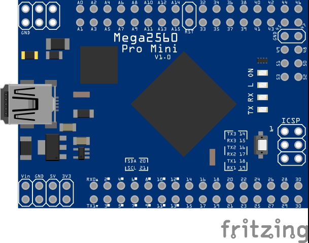
So i could have a better grasp
Thanks !

I need to build a circuit like this on the Breadboard of Fritzing... Can someone help?

$
0
0

I could, but you won't learn anything if I do it :slight_smile: . You are almost there now. You can change the wiring in breadboard to match the schematic you have or recreate the schematic in schematic view and use that to wire breadboard either will work.

Peter

I need to build a circuit like this on the Breadboard of Fritzing... Can someone help?

Save Problem on my PC

$
0
0

Hey,
At first thanks for your help :slight_smile:
I have just one user on my PC so I hope that can not be the problem.
I tryed the debugging here the last text:
current path: C:/User/simon/Desktop/Fritzing/fritzing.0.9.3.b.64.pc
current file: Untitled Sketch.fzz
I hope you can help me
Thank you

I need to build a circuit like this on the Breadboard of Fritzing... Can someone help?

$
0
0

Better but still not there. You need a connection from the cathode of the second diode (the end row) to ground (black wire from the battery) above it. The 100K resistor is currently shorted. All 5 pins on the top row short together shorting out the 100k resistor. Easiest solution would be to rotate the 100k resistor 90 degrees so it connects to the ldr lead with one end and the current row with the other. Then you should be away.

Peter

Viewing all 31021 articles
Browse latest View live


<script src="https://jsc.adskeeper.com/r/s/rssing.com.1596347.js" async> </script>