Development on Fritzing is mostly stopped. A few of us are trying to fix some of the bugs but it is going slowly. Your best hope (other than getting the source and trying to do a port yourself) may be the project on github to move Fritzing to a web based javascript/css environment but it is at a very early stage at present.
Steps I took that resulted in the problem:
Extended stripboard beyond the default value. The extended area is created as all tracks connected matrix, not strips.
What I expected should have happened instead:
Stripboard with strips appearing to extended area
My version of Fritzing and my operating system:
Win 10 64 bit, 0.9.3b
Please also attach any files that help explaining this problem
It helps to do a search for your problem before posting. All it took was a search for the word stripboard in the forum and the first result was Stripboard / Veroboard extension not working correctly and it has almost exactly the same title as yours so it is likely the forum suggested it as an answer when you started to type in your title.
Hi all,
for my actual project i’m using a Recom R-78E5.0-0.5 SIP3 switching voltage regulator.
Sadly i couldn’t find that part in fritzing Image may be NSFW. Clik here to view.
Is there anything similar i can use for creating a pcb with this part or have i just missed it?
I had a look at the datasheet and it looks to have three pins spaced on 2.54mm centers. That means you could use a mystery part or generic header set to three pins and hide the silkscreen. You would have to use your imagination and some math to make sure you have the clearance around it. If you wanted the silkscreen you could draw a square with inkscape and then import it into fritzing using the silkscreen image part.
I think they are still used around here since those are for educational projects at most electrical careers. Good one Image may be NSFW. Clik here to view.
I’m trying to build a strobe - it used to be popular 30 years ago - to check ignition timing, but when I look for small transformers, 600V caps, Xenon bulbs, trigger transformers, there aren’t many, or at least a good selection, on Ebay/Ali or at my local store.
Go to your local thrift store or pawn shop and get some old film cameras with built in flashes. They have everything you need. You used to be able to go to photo finishing places and get the used disposable cameras with flashes for free.
I saw some strobe projects online using a camera flash, but I thought that they might not be readily availible to everyone.
What I’m trying to do is come up with a simple cheap circuit with easy to find parts so poeple can set their timing when trying to start their car using the Arduino ECU project - the whole project is about cheapness -. I found 1 circuit that doesn’t use many parts, so I’m testing that.
I have a simple LED timing light working, but it has problems and is rather weak. This one is cheap and only uses 11 easy to get parts, and if I can make it better I won’t worry about the Xenon strobe.
A 7805 voltage regulator will give you the pads and a mostly suitable schematic. The silkscreen on pcb will be a little small as your module is wider than a TO220 case. If you need the real outline in pcb it is easy enough for me to modify a copy of the 7805 to match (it may be less easy for you Image may be NSFW. Clik here to view. ).
If you are using standard white LEDs (I’d be tempted to start from a 5 or 9 led ebay type battery flashlight to get the leds a case and reflector to get a directed beam that may be bright enough) you should (note the weasel word Image may be NSFW. Clik here to view. ) be able to get more brightness by increasing the voltage driving the LEDs to source more than their rated current with a short on long off cycle. Light output is linear with current (but at some current point the internal bonds may melt) and the short duty cycle keeps the heat (which is usually the real limiting factor) within bounds. The newer multi watt white leds I think use a phosfor to adjust the light output spectrum and thus may not turn off fast enough to do what you need (simulate the bright fast output of a strobe tube), but I think the standard 5mm type white leds that come directly from the die should probably work. You may need to drive it from a power MOSFET to get the current you need though.
As well I assume you have seen
While it wouldn’t be that difficult to make a custom part for this device, a look at the data sheet indicates that the embedded antenna (which I think is needed for this particular part as it doesn’t have the connectors for an external antenna) needs a 4 layer board which Fritzing doesn’t support, so I’m not sure the part would be usable in practice. I suspect you want the part that supports an external whip antenna via the ufl connector but which has a different pcb footprint than the part you referenced. Both the referenced part and the one with pads for the antenna appear to need 4 layer boards.
That remined me that have an old junkshop 7 LED torch, but after testing it wasn’t that bright. I also have a new COB torch which is bright, but if phosphor has lag it’s probably not ideal.
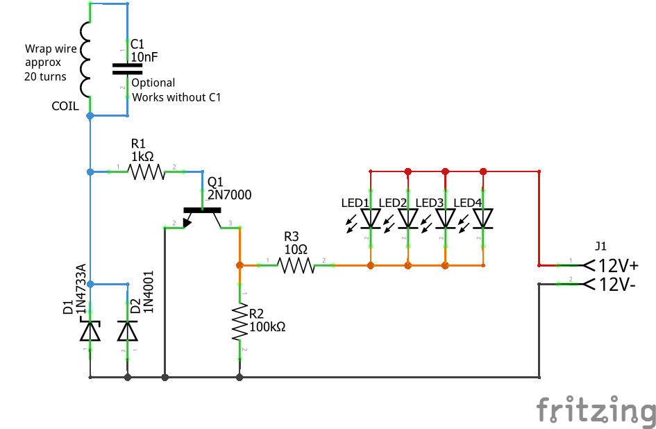
The circuit runs on 12V and only has a 10 ohm resistor, so I guess it’s already using a low duty cycle. Image may be NSFW. Clik here to view.
It’s hard to see in the video because the frame rate doesn’t match the strobe - eye was clearer - , but the Xenon TL showed the mark a touch below the dot on the VR sensor. The LED on the other hand was very close, but the problem is it showed 2 marks. One mark looked on the right spot, but the other looked about another 10º retarded - the vid kind-of shows the 2 marks -. Because it uses a wire wrapped around an ignition lead it must be retriggering with flyback. If you use the most advanced flash it should be good enough.
I’m going to try more LEDs, the 10mm LEDs, and I see if the COB has lag, when they get here.
That is correct, but the module specified appears to need an on board antenna (it isn’t on the module) and the antenna needs a 4 layer board that AFAIK Fritzing won’t make (leaving aside the difficulty of creating such an antenna in Fritzing). The version with a connector will take a whip antenna (and I think, but am not sure, not need the 4 layer board) but that isn’t the footprint he asked for.