Thank you for your answer Peter,
I found how to modify, cut or add tracks
Tomorow i will post a screenshot of my work.
(For me , the links of vidéo are also broken)
Please, another question:
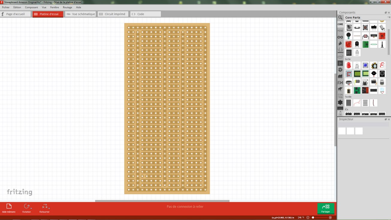
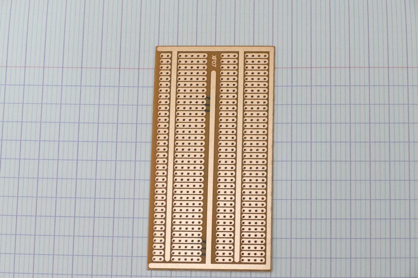
I think it’s the printed circuit board that we see, so how to display the streapboard components side in Fritzing ?
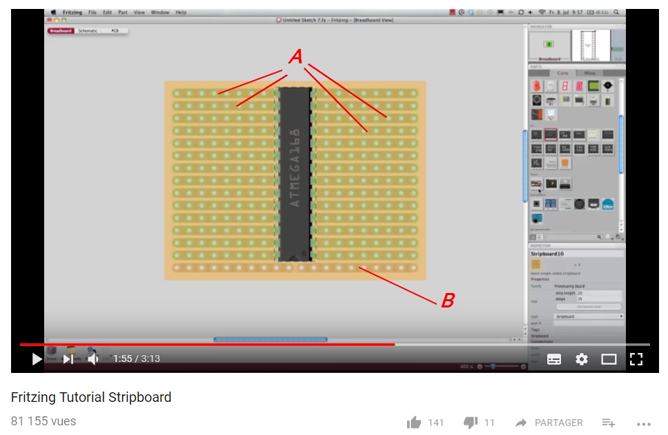
How to créate a streapboard the same like in the picture?
How to créate a streapboard the same like in the picture?
Unfortunately you can’t in breadboard. To view both sides you need to do it in pcb view (and the strip boards aren’t created there so you have to create them), breadboard only shows the view from above.
Peter
Small Transformer 14x19x15h
It seams to be latching. I’m using a wire as a switch and when I close it the LED goes on, but when I open it it stays on.
EDIT
After playing for a while the 555 caught fire, so I tried another and it flashed the LED once and stopped working. 2 more blown 555s and I put the diodes back, and this 555 looks like it turns the LED on and off instantaneously - no lag - with the wire switch.
Back to my old 80s 555(tested in my simply osc circuit) and it latches, but another 80s 555(tested in my simply osc circuit) does the on and off instantaneously.
The Ebay 555 could be fakes, but it seams thay they latch or don’t delay the off.
EDIT EDIT
The working Ebay 555 blew so back to the latching 555, and now if I tap the wire quickly to GND it flashes a little. I think I have to get some new 555s of better quality.
Small Transformer 14x19x15h
For testing you may want to try something like a 10uf cap as C3 (plus towards pin 6/7) and 47K as R2 to give you a long time constant (around .5 sec) of output pulse. Then a tap on the trigger should give you a fairly long led on time before it goes off. With a short output pulse it may be hard to tell if it is working or not (although it does sound like you have some bad 555s).
Peter
How to créate a streapboard the same like in the picture?
Hum-900-prc part
I think this part should work for the -ufl or -cas versions of the part (but I think only the -ufl version will work with Fritzing) as the footprints are the same. Schematic and labels are for the -ufl version (-cas ant pin is NC as the ufl connector is the antenna). As always you need to verify the footprint against a real part before ordering boards because I don’t have one.
man-hum-900-prc_Module.fzpz (11.4 KB)
Peter
How to créate a streapboard the same like in the picture?
Yes that looks to be correct in this case (although this strip board looks to be a custom part to do that, the standard strip board won’t do this). There aren’t actually two layers in the drawing, a wire connected to the B strip in breadboard will be the same as a wire connected to an A strip, the different color of the trace is the only difference that makes it appear to be two layers, Fritzing only recognizes one layer in breadboard. Perhaps I misunderstand what you want to do, but in breadboard you can only look down from the top of the board (I had assumed you wanted to flip the board so you are looking at the bottom side which Fritzing won’t do.) The board above appears to have been created as a custom part with a different color used for the bottom layer on one strip. It isn’t clear to me why you would want to do this because you can’t see or connect to the bottom pads (assuming they are there) under the IC. Wires (in breadboard) will only connect on the top of the board like this:
You can’t run the wires under the chip or flip the board to see the wires on the bottom side of the board or have a different wire connect to the bottom of a board (Fritzing will connect it to the top layer, the only layer it recognizes).
Peter
How to créate a streapboard the same like in the picture?
Thank you for your explanation !
I wanted to be sure that when I put a component on the streapboard with Fritzing, it would be the same in reality with my plate. (That it would be well disposed)
Another small question:
are there smaller components or semi-transparent components that could be created for streapboard?
This what y have créated on Fritzing :

…

How to créate a streapboard the same like in the picture?
I’ve made some parts which are available here in the forums (I’ve been so far too lazy to submit them on github to get in to core parts) of parts that are shrunk for perf board use as have other people, what I didn’t do is keep a list of them, so you need to search. It is mostly LEDs, TO220 cases in various sizes. to92 transistors and capacitors so far I think. Most of mine have “top view” as a tag I think so searching for that may help. If you need something that isn’t done yet, post and I’ll look at how easy it is to do (it is usually not too bad if you are used to making Fritzing parts).
Peter
Does an Arduino Uno Mega Shield SD Card ICSP SPI Exists Already?
Hi,
Very new to Fritzing, it is awesome! Thank you.
I have a test shield for the Uno that has a built-in SD card. My project has exceeded the capacity of an Uno and was looking to use a Mega 2560. Plugged in my card only to find the SPI pins on the mega have moved to the ICSP header. Most of my shields use the SPI pins on the Uno, 11, 12, 13 I believe they are…
It seems one can make an adapter shield with jumpers of some sort that can ‘map’ the functionality of the SPI pins between 11, 12, 13 to the ICSP header, maybe another setting to make the pins pass-thru to other shield, etc.
Before going down this path, surely someone has done this already or there is some obvious problem that I am missing.
Let’s say I have to make one or decide to make one of my own for whatever reason… The ICSP header I would want to use would be a long pinned female type connector pass-thru hole … ? I did not find this part in the large list of parts. Am I missing it?
Lastly, if I add my own SD card, is there a chip of some sort needed? Or do the pins go directly to the ICSP pins? My existing shield looks like it has a real small ship with no markings that I can see.
Thank you!
Small Transformer 14x19x15h
I got some new TI 555s and had to use 100uf for C3, but only the first press has a delay. You press it the 1st time and it stays on for 3 sec, but any press after that and it’s instantaneous again. You have to dissconnect the power and reconnect, and it does the 1st press delay and 2nd instantaneous again. I tried holding the button on longer, to maybe charge the cap, but it makes no difference.
How to créate a streapboard the same like in the picture?
That original pic is of a very old version of Fritzing, and the darker greenish tracks “A” are indicating it’s connected to the IC. Not top/bottom. AFAIK all stripnoards are single-sided on the bottom only, so no need to show tracks on the top.
You can make a stripboard in PCB, but it is a bit difficult. You set grid to 0.1", and use vias and linking traces. You can do small sections and duplicate them, but it is a bit tricky.
Small Transformer 14x19x15h
That would indicate that pin 7 (discharge) isn’t working. When the output goes low again (and the LED goes off) pin 7 should go to ground and discharge C3 to prepare for the next cycle. For some reason that isn’t happening. It may be worth putting your scope on pin 6/7 and see if the waveform there looks like the diagram in the tutorial (I suspect C3 is staying charged from the symptoms) . I’ll see if I can find a 555 around here somewhere to experiment with.
Peter
Small Transformer 14x19x15h
Damn, cheap Ebay parts caught me out again. Last year I made a circuit on a BB that didn’t work and after a lot of struggling I traced to the short blue wires that came in the Arduino kit, which had resistance , so I stopped using blue. I used a green for this one, but I thought I better change it out just incase, because it links pin 6 to 7. Looks like that fixed it because it now delays all the time.
Sorry about that.
Small Transformer 14x19x15h
OK with that working, now this should get the trigger working correctly I think:
The 560K/ 330K (R3/R4) voltage divider should provide around 4.4 volts with no voltage from the coil. The 555 trigger voltage should be 1/3 of 12V or about 3.6V so if the coil manages to produce at least -1 V (and the larger value resistors should let it do that I hope, if not we can increase the size of R3 and R4) that should trigger the 555 and you should be able to stretch the pulse so you get both enough light without overloading the LEDs and enough time on the output pulse to ignore the second trigger you were seeing. You will need to adjust the R2/C3 values to get the appropriate length of pulse for what you need,
Peter
Does an Arduino Uno Mega Shield SD Card ICSP SPI Exists Already?
Since this is the only part I know anything about I’ll answer this. The SD cards are all 3.3V as far as I know so assuming your Mega is running at 5V the chip is likely a 74ahc125 (I made a Friting part for this that is available in parts submit). The 74ahc125 with VCC at 3.3V will tolerate 5V from the Mega on its input pins (unlike the SD card) and output the signal at 3.3V to the SD card. Putting 5V in to the SD card may damage the card.
Peter
Small Transformer 14x19x15h
I’m confused about the junctions - I know you don’t use FZ much -, but is the link from R4 to C1 jumping over the link from pin 2 to the pickup wire L1, or connected to it, ie a 4 point junction.
How to créate a streapboard the same like in the picture?
Small Transformer 14x19x15h
You are right there should be a dot at the r4 /L1/C1 junction as R4 should connect to the trigger line. I missed that when I modified the drawing. The idea is when the coil is not active (due to no spark) the R3/R4 junction (and therefore the trigger) will be about a volt higher than the trigger level. The spark will hopefully cause at least a volt or 2 of change in the coil which will drive the trigger below the threshold and trigger the 555 to extend the pulse.
Peter
How to créate a streapboard the same like in the picture?
Not directly in breadboard. Inside Fritzing there are different svg (a graphic format) files for each view. Typically the ones used for breadboard have been made to look like the component tilted at about 45 degrees. As you have found this is inconvenient with strip board. Therefore for the parts I and others have made for top view for strip board we change the svg for breadboard to look more like the silkscreen in pcb view. Unfortunately it isn’t automatic, we need to create a new part then edit the breadboard svg file with an svg editor such as Inkscape to make the change. That is a fairly complex process until you get used to doing it so it is usually easier to get one of us to do it for you (although learning to make parts is a useful skill if you like Fritzing).
Peter


