Quantcast
Channel: fritzing forum - Latest posts
Viewing all 28594 articles
Browse latest View live

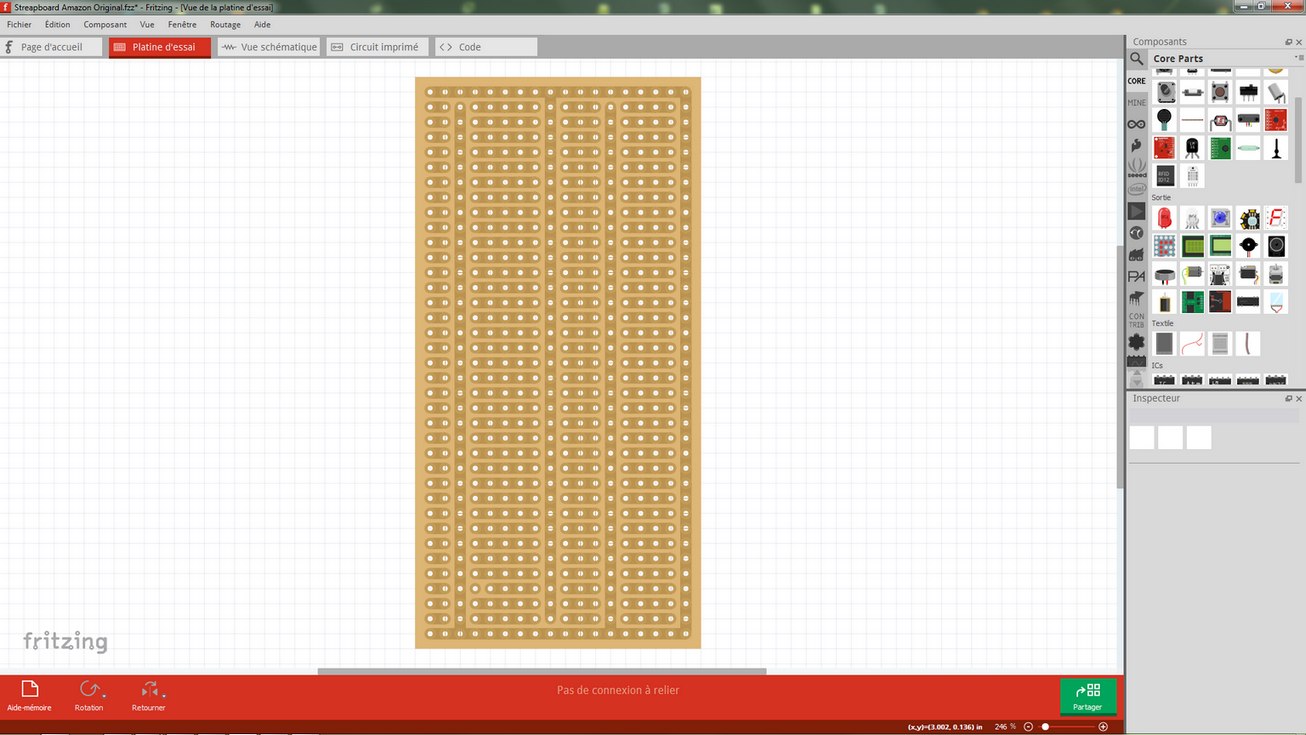
How to créate a streapboard the same like in the picture?

$
0
0

If you export this image as an SVG you could use it as a picture in PCB view. That would let you use PCB view but would not let you unlink the bars as they will only be a picture. You could just draw traces between the pins you want connected and those would let you know which bars to disconnect in real life.

After exporting the SVG you would crop the picture to be just the board. Then delete the original PCB in PCB view. After that find the PCB silkscreen image part in the core bin and place it in PCB view. Then in the inspector change the image to be the image you cropped. After that set its origin to 0,0. Last thing is to make sure the grid size is set to 0.1" (2.54mm) and that snap to grid is turned on.


Small Transformer 14x19x15h

$
0
0

Junctions are a bit tricky but you make them by holding down the ALT on the keyboard and clicking on a bendpoint, and that starts a trace that you drag to the pin. As usual grab the junction and move it and all the traces should move - this test doesn’t work for 4 junctions because only 3 move at a time -.

I corrected all the junction and made this circuit, but it’s inconsistent, ie sometimes it latches and needs a reset, sometimes it’s instantaneous. I still have the switch connected to GND pin2, but practically every button press is different. If I cut the wire where the label is, every button press is as expected.

Timing_light_new5.fzz (11.9 KB)

Does an Arduino Uno Mega Shield SD Card ICSP SPI Exists Already?

$
0
0

Thanks Peter. I am using your part. Can you kindly tell me what pins go to what pins? I’ve never used a buffer before. Nothing on Google came up when looking for SD card and 74ahc125.

Small Transformer 14x19x15h

$
0
0

What happens if you short the coil (i.e. remove L1/C1) leaving R3 connected to R4 and pin2? That should work as normal (if the resistor values are correct) as pin 2 should be about 4V which should be just greater than the trigger value. Shorting R4 with a jumper should then trigger the circuit as now. If it is inconsistent without the coil in there then the R3 value is likely too low and needs to be 680K instead of 560K (to raise the voltage at pin 2 above the trigger voltage). The latch up is strange though, I’d expect it to always trigger or never trigger not latch up. It may be worthwhile to put a capacitor between ground and VCC to make sure current spikes aren’t causing VCC to drop, but I don’t think we are drawing enough current to make that likely.

Peter

Does an Arduino Uno Mega Shield SD Card ICSP SPI Exists Already?

$
0
0

Here is a schematic (note that the part needs to be a 74ahc125, none of the others such as the 74hc125 will do level translation which is what you need.)

The part has tristate outputs, so the enables are all tied low so the output is always enabled. What you are doing here is 5V to 3.3V level translation, but there isn’t all that much information about it available on the net for some reason. I found the 74ahc (only some parts in the series though) explaination in a TI application note on level translation. There are also other level translator chips available but this one is cheap and easy for this application.

Peter

Small Transformer 14x19x15h

$
0
0

That’s pretty much the same as when I cut L1, because I have a button that shorts R4 to GND. The only difference is C1 is replaced with a jumper.
Replacing C1 with a jumper makes the LED latch on button press.
Changing R3 to 680K makes the LED stay on even before the button press. But putting C1 back makes it somewhat normal again.

Small Transformer 14x19x15h

$
0
0

Can you measure the voltage at pin 2? In theory the trigger voltage should be 1/3 of 12V or about 3.6V. What I am trying to do is get the rest voltage (with no pulses from the coil) 1 V or so higher than the trigger voltage so it should trigger with 1 or 2 V less from the coil. Its possible that the trigger voltage isn’t doing that for some reason (such as the trigger pin is drawing current and lowering the voltage which I don’t think it should be).

Peter

Does an Arduino Uno Mega Shield SD Card ICSP SPI Exists Already?

$
0
0

If you are just looking to add a Micro SD card to an Arduino Mega you should just get an SDramps board. http://reprap.org/wiki/Sdramps

They are really cheap on eBay and other places that sell 3D printer parts.

$1.79 USD with free shipping from fasttech.com


Small Transformer 14x19x15h

$
0
0

Damn, I had my pin 2 at the junction of R3 and C1, which worked somewhat, but now that I move it down to C1 R4 the LED stay on all the time. With that config, LED always on, it’s 180mv from pin 2 to GND. I don’t know if this is right but the other side of C1, the C1 R3 junction, it’s 11.4V.
Replacing C1 with a link shows 4V at R4 R3 pin 2 junction.

PS : Is this annoying yet :slight_smile: Because i bet if you were here you could fix it in 1 min.

Df robot ph sensor

$
0
0

First of all thank you very much!
But there’s a problem that i can’t solve…i’ve imported the file PH_meter.fzpz and now i can’t install the last .fzpz on this page because the program says “there’s already a part with ID… loaded into fritzing”…what can i do?

Df robot ph sensor

$
0
0

You need to right-click remove the orig part from MINE bin, restart Fritzing, and then install the new .fzpz.

Or you have to remove the part from - C:\Users\X\Documents\Fritzing\parts\user

Df robot ph sensor

$
0
0

Solved! Thanks!
last question…have a look here…https://www.dfrobot.com/product-1025.html
the photo with the three components…the one with the three wires together (the blue,the black and the red) am i able to find it somewhere?
Help and thanks!

How to créate a streapboard the same like in the picture?

$
0
0

Thank you for your answers to both, Peter and sublimeartistry.
It’s very kind of you to give me ideas and proposals but it’s too difficult for me.
There is very little French tutorials about Fritzing and I understand not very much English language.
Sorry, but I’ll settle for that, never mind!

Small Transformer 14x19x15h

$
0
0

Two problems here (one of them mine :slight_smile: ). The resistor values are a bit wrong, it looks like the 555 draws current on the trigger lead so R3 should be 560K and R4 should be 680K. For me that makes pin 2 6.3 V and grounding pin 2 then reliably triggers the 555 (I dug one up and tried it!) Initially I saw the same problem as you: the 555 would trigger once and then hang. It turned out my C3 (a tantalum cap) was defective. With pin 6/7 disconnected the capacitor was only getting up to about 4V (likely due to leakage in the cap) which isn’t enough to trip the high side comparitor reliably. When I replaced the cap with one that gets close to 12V with pn6/7 disconnected the circuit started working. It would be worth disconnecting pins 6/7 and making sure the R2/C3 junction gets close to 12 V as it should. From the voltages you quote (.2V at pin 2 which is low and thus continuously triggered and 11V at R3) your problem is the coil is disconnected between R3 and R4. There needs to be a DC path (either the coil or a jumper across where the coil should be) so the voltage divider functions. The coil (if it isn’t seeing any sparks) will be basically 0 ohms and not affect the voltage divider. When a spark happens the voltage induced in the coil is supposed to drive pin 2 lower than 3.6 volts and trigger the 555. Hopefully the 560K/680K resistors are large enough that the coil will produce enough voltage to cause the trigger. As noted above you should be seeing about 6.3V on pin 2 of the 555 with it not triggered. If I reduce R4 to 390K (which produces 4.3 v on pin2) the circuit triggers once and then hangs, so it looks like there is some slop in the supposed 3.6V trigger threshold. Hope some part of this helps! Who knew 555 circuits were this complex :slight_smile: , they usually just work. Once this circuit works with grounding pin 2 reliably then the excitement will be if the present coil provides enough voltage to reliably trigger the 555. If not you may need to increase the number of turns on the coil to get more voltage.

Peter

Df robot ph sensor

$
0
0

There likely isn’t a part like that available as it is an interconnecting cable with connectors on both ends. In Fritzing we would usually just connect wires to the board. Assuming you want it only in breadboard (with no connectors as it isn’t easy to connect them to anything) a custom part could be made by copying the connector from the board twice and putting wires of the correct colors between them. They won’t show in schematic or PCB as the connections are fairly difficult to do.

Peter


How to créate a streapboard the same like in the picture?

$
0
0

Google translate can sometimes help with translations (we often use it to answer questions in other languages). In any case if you have more questions or need help feel free to ask and we will answer as best we can.

Peter

Small Transformer 14x19x15h

$
0
0

Yay, the LED blinks when the spark plug is firing.

I went back to 10 ohm for R1 - it was 1K - and it’s brighter, but I might increase that a bit. With my cheap Ebay scope I get 1V across the LED with 1K but 7V across the LED with 10 ohm.

EDIT - 50 ohm makes 3V.

Bendable Legs disconnect part when moved

$
0
0

Steps I took that resulted in the problem:

It’s probably not worth reporting, but if you complete the SCH with it’s connections and go back to BB view and bend a leg, that parts becomes disconnected.
In fact if you do SCH view first and try to do BB after you can’t grab legs on small pin parts to bend them because the mouse click always grabs the ratsnest first.

What I expected should have happened instead:

Part stay connected in the circuit

My version of Fritzing and my operating system:

v9.3 Win7 64

Please also attach any files that help explaining this problem

Small Transformer 14x19x15h

$
0
0

Good news! With that working now you can adjust the duty cycle and LED resistor to get as much light as possible without burning out the LEDs. Even a cheap scope is a huge step up from no scope and while I don’t have one (I paid a couple of grand for a real Tek scope 25 years ago or so, excellent investment!) the 138 type Ebay scope looks pretty good for the price.

Peter

About the parts submit category

$
0
0

Parts for

  • EBYTE E73-2G4M04 bluetooth module
  • MOLEX KK 10 pin PCB connector
  • TAG CONNECT TC2030
Viewing all 28594 articles
Browse latest View live


<script src="https://jsc.adskeeper.com/r/s/rssing.com.1596347.js" async> </script>