Quantcast
Channel: fritzing forum - Latest posts
Viewing all 28594 articles
Browse latest View live

Small Transformer 14x19x15h

$
0
0

I wouldn’t mind a real scope, because the DSO138 certainly comes in handy, it’s just that I would never use it enough to justify the price. Oddly enough I don’t use the waves that much, more the displayed values like frequency and voltages.

The 10mm LEDs came in so I just have to wait for the COB and I will test in on the car all at once, because it too hard doing multiple setups.

Thank for your help, because I’m definitely not smart enough to design circuits - I’m more monkey see monkey do :slight_smile: -.


How to créate a streapboard the same like in the picture?

$
0
0

Yes, i used many times Google translate for your messages and for answer to you !
Many thanks for your help and for the next , perhaps :cowboy_hat_face:

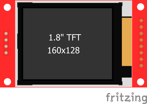
Searching for ST7735B - 128x160 TFT LCD Display part

$
0
0

Anyone done this display ?
It is very similar to the AdaFruit 2.0 except that it is 8 instead of 9 pins and slightly smaller.
I tried editing the AdaFruit 2.0 but I am clueless with the parts editor

Searching for ST7735B - 128x160 TFT LCD Display part

$
0
0

There doesn’t seem to be one, but because (at least for me) it is an easy mod this should do what you need. As always if you are making a PCB you need to check the footprint (the mechanical drawing I found online isn’t all that complete and the 4 pin header may not be aligned quite correctly). Note to use the SD card you need to populate the 4 pin header (as the SD card doesn’t seem to connect to the 8 pins for the display).

TFT 1.8 inch 160x128 w SD.fzpz (8.7 KB)

Here us a copy of bb view so others can see if their card matches without downloading the part:

tft_bb

Peter

Does an Arduino Uno Mega Shield SD Card ICSP SPI Exists Already?

$
0
0

Peter, Thank you for the detail. I have added it to my board.

Does an Arduino Uno Mega Shield SD Card ICSP SPI Exists Already?

$
0
0

That is an interesting option. Happy to see only 1 chip on there, looks like a diode. Was thinking I needed some caps on there guess not.

Arduino shield and ICSP Headers

$
0
0

I am making an Arduino shield of sorts. It is almost ready but I need a couple parts to finish it off.

Is there parts out there for the Arduino headers with the long pins and female headers? Same for the ICSP pins?

If not, I’d like to just leave the usual solder holes and I’ll source the parts myself. I cannot seem to find a simple hole for soldering pins on a through-hole component. I find the mounting hole object.

Thanks!

Arduino shield and ICSP Headers

$
0
0

In the core parts bin near the bottom with the label connection the first icon (a single .1 connector) is what you want. If you drag that in to a view then Inspector (the lower right window) will let you change its attributes (number of pins, male / female etc.) to make most headers you could want. It will create the correct footprint in PCB view for the selected connector. The long pin version isn’t available but the gerneric version will work fine.

Peter


Searching for ST7735B - 128x160 TFT LCD Display part

$
0
0

Thank you.

I wish editing parts was as easy for me.
Trying to mod the closest AdaFruit Part proved disaterous.

BTW there are several TFT’s with this footprint or one very close.

One thing people should be careful of is whether they have a 5v or 3.3v board.
Or on that can do either.

The image looks correct.
I will try to check the 4 pin SD header - though I do not use that header myself.

I like this part because it is cheap easy to program and can be used for most any device that supports SPI.

I would prefer it did NOT have the SDcard. but the displays without it are more expensive.

Again thanks.

Does an Arduino Uno Mega Shield SD Card ICSP SPI Exists Already?

$
0
0

I often use sdCard adapters on Arduino (UNO, Nano, and Atmel chips on a PCB or Breadboard). I just finished an indoor lap counter (to count laps I jog in the house 14 laps = 1/4 Mile… LOL)

A summary of what I’ve learned: Using something not specific to a board/device has worked the best for me for these reasons:
• Can use different pins
• Vin = 4.5 to 5.5
• They have their own 3.3 Voltage regulator
• They work with the varioius Arduino sdCard libraries
• 5 units for about $8

These are one’s I buy from Amazon: SenMod sdHC Adapter

Two example projects (one has an Audio Amplifier on the PCB)

Does an Arduino Uno Mega Shield SD Card ICSP SPI Exists Already?

$
0
0

Well my PCB prototype is complete! If the SD card doesn’t work I’ll swap it out for the pre-done ones that are mentioned here. It would probably make my PCB single sided too. Hmmm…

Now to get the parts…

Thank you all!

Df robot ph sensor

Xenon Timing Light

$
0
0

Sorry, back again

I made this circuit based on a vid from The Signal Path because it’s simple. The circuit has to be simple, cheap, with easy to find parts.

When I apply 5V - voltage doesn’t makes much difference - it only puts out 55V across C1, when I need 300V.
The only transformers I could find were in old transistor radios, so is the transformer wrong?
I did some Googling and it said the only way to work out unknown transformers is test and measure.

Just the power side so far.

Original

Xenon Timing Light

$
0
0

I must say I don’t really understand how that circuit works. It looks like it makes a half wave input which could be why the output is so low.

I have done a lot of work with Nixie tubes and VFD displays that require high voltages and the simplest HV power supplies are usually inductor-based boot converters. Here is a simple one with production files and schematic http://www.smbaker.com/high-voltage-power-supply . You can find other ones in the files section of Neonixe group https://groups.google.com/forum/#!forum/neonixie-l

A few others I had in my bookmarks.
http://www.desmith.net/NMdS/Electronics/NixiePSU.html
https://reibot.org/2011/08/07/intro-to-boost-converter/ .

I use these tiny ones in watches. For $9.99 it is hard to make it cheaper and impossible to make it smaller. It is also transformer based so more efficient than the ones above. https://www.ebay.ca/itm/type-c-5vin-170vout-hv5w-high-voltage-nixie-power-supply-module-nixie-tube-era/141728914580?hash=item20ffb39c94 they make many other models including variable and higher amperage versions. I also have a list of many other small ones on eBay here https://www.ebay.ca/cln/sublime_kustoms/Nixie-Power-Supplies/385065490015

Sorry to not offer much help with the circuit.

Xenon Timing Light

$
0
0

I’ll have to read all that, but this is from a disposable camera so must be the simplest.

It’s explained here.


Xenon Timing Light

$
0
0

Could it possibly be that your text equipment is just too much of a load? Nixie tubes only run at 2 - 5ma.

It could also be that you need the neon indicator tube as part of the oscillating circuit. Their properties can actually be used to create a logic circuit due to the difference in the ignition and maintaining current requirements. http://www.dos4ever.com/ring/ring.html

Xenon Timing Light

$
0
0

Yes your likely problem is the transformer turns ratio. I’d guess this is an 8 ohm output transformer with an about 80 ohm secondary from the voltage you are seeing. For 5V in and 50v out you have about a 10/1 turn ratio (which translates approximately to the impedance ratio of 8 ohms to 80 ohms). The transformer you need wants a 80/1 or so ratio to increase 5V to 400V. I think the value of the capacitor (and possibly the impedance of the transformer) will control the oscillation frequency of this (it is quite a clever simple oscillator circuit I must admit!). Note that you need 1kv of isolation which tends to be expensive (a 100V isolation is in the $2/$3 range for 600ohm/8ohm, 1KV isolation is $14 or more). What might work best is a 220volt to 6V power transformer. If you feed the 6V side with 12V the line side should produce 440V. I’m not sure this oscillator circuit will work (it would need to be in the 50/60hz range to work correctly) but a 555 oscillator at 60hz driving a MOSFET in place of the transistor should work. Note you want to be careful around the 400V output, with the cap that is getting to be enough energy to kill you if you touch it.

edit: One of these may do as well, somewhat pricey and shipping may be an issue

Peter

Xenon Timing Light

$
0
0

So that’s how you work out transformers. This is 1-ish ohm to 14-ish ohms - my DMM doesn’t seam that accurate - but my cheap Ebay transistor checker shows 3.2mH to 32.8mH which is close to 10:1.

It’s hard to find small transformers on the cheap sites, and even harder to get specs - my local only gives mH of the windings -, and expensive is kind-of a deal breaker because the whole timing-light is $27AUD.

I’ve got a 240V to 5V USB I can try, but like you said it needs an osc because it’s only 2 wire on the secondary.

EDIT - I just found 1 under High Voltage Transformer, it’s just that it’s 10KV. It has a lot of wires, so here hoping I can get to down to 300V.
https://www.google.com.au/search?q=Booster+Coil+Inverter&client=opera&hs=Mxz&source=lnms&tbm=isch&sa=X&ved=0ahUKEwjU4azg7dnaAhWMvbwKHerNBpQQ_AUICygC&biw=1440&bih=803#imgrc=C-ipvtYqyQO8fM:

Xenon Timing Light

$
0
0

Actually you can’t really use the resistance to determine the windings. Both windings are most likely wound with different wires (thicker for low voltage side, the thinnest possible on secondary). This means the resistance for 1 wrap of one side will be different from the resistance of 1 wrap on the other side. The only way you can actually tell is to input a known full wave AC voltage and measure the output.

Hum-900-prc part

Viewing all 28594 articles
Browse latest View live


<script src="https://jsc.adskeeper.com/r/s/rssing.com.1596347.js" async> </script>